Introduction Take notes for the computer structure and write down the knowledge points in each chapter
Chapter 1
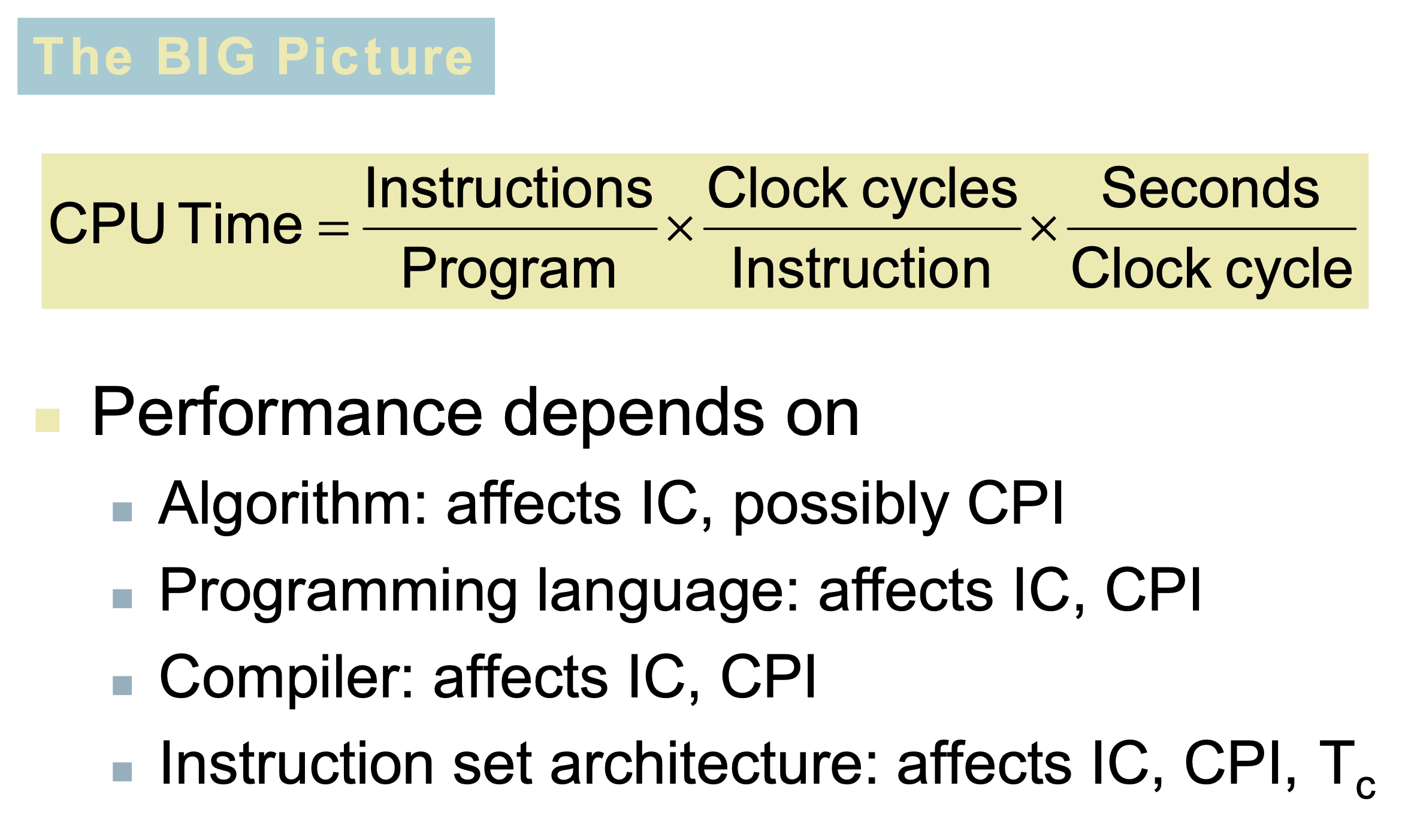
Main formula
CPU_TIME
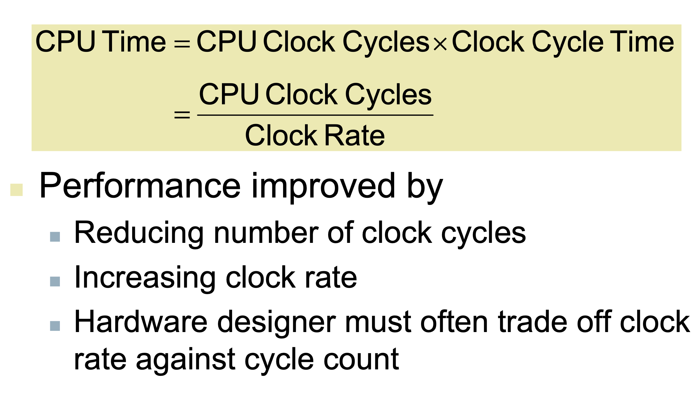
CPU TIME = execution time
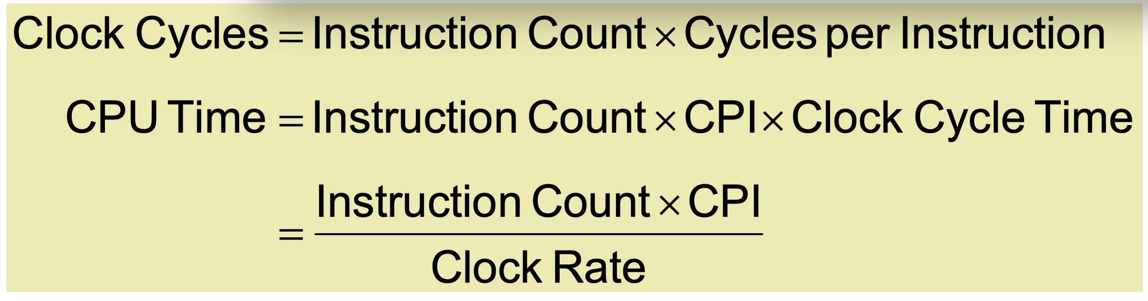
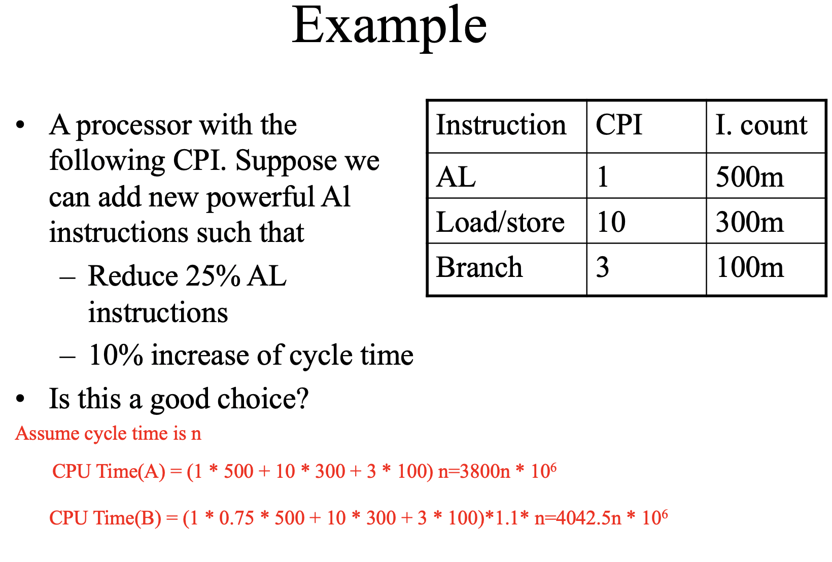
CPU TIME = instructions * CPI * cycle time
CPU TIME = (instructions * CPI) / clock rate
CPU TIME = clock cycles / clock rate
CPU TIME = (Σ(instructions * CPI)) / clock rate
Instruction Count & CPI
instructions = clock cycles / cycles per instruction
instructions = CPU TIME / CPI / cycle time
instructions = CPU TIME * clock rate / CPI
clock cycles = Σ(instructions * CPI)
clock cycles = instructions * CPI
CPI = clock cycles / instructions
CPI = Σ ( CPIi * (instructionsi / instructions))
BIG Picture
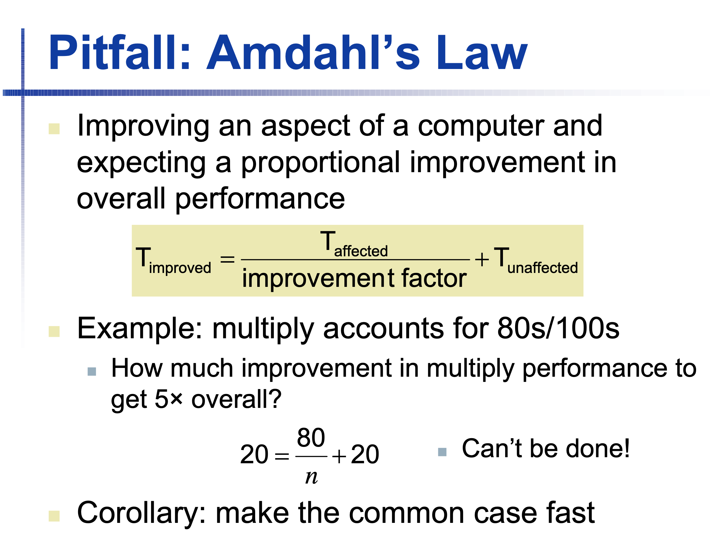
Pitfall: Amdahl’s Law
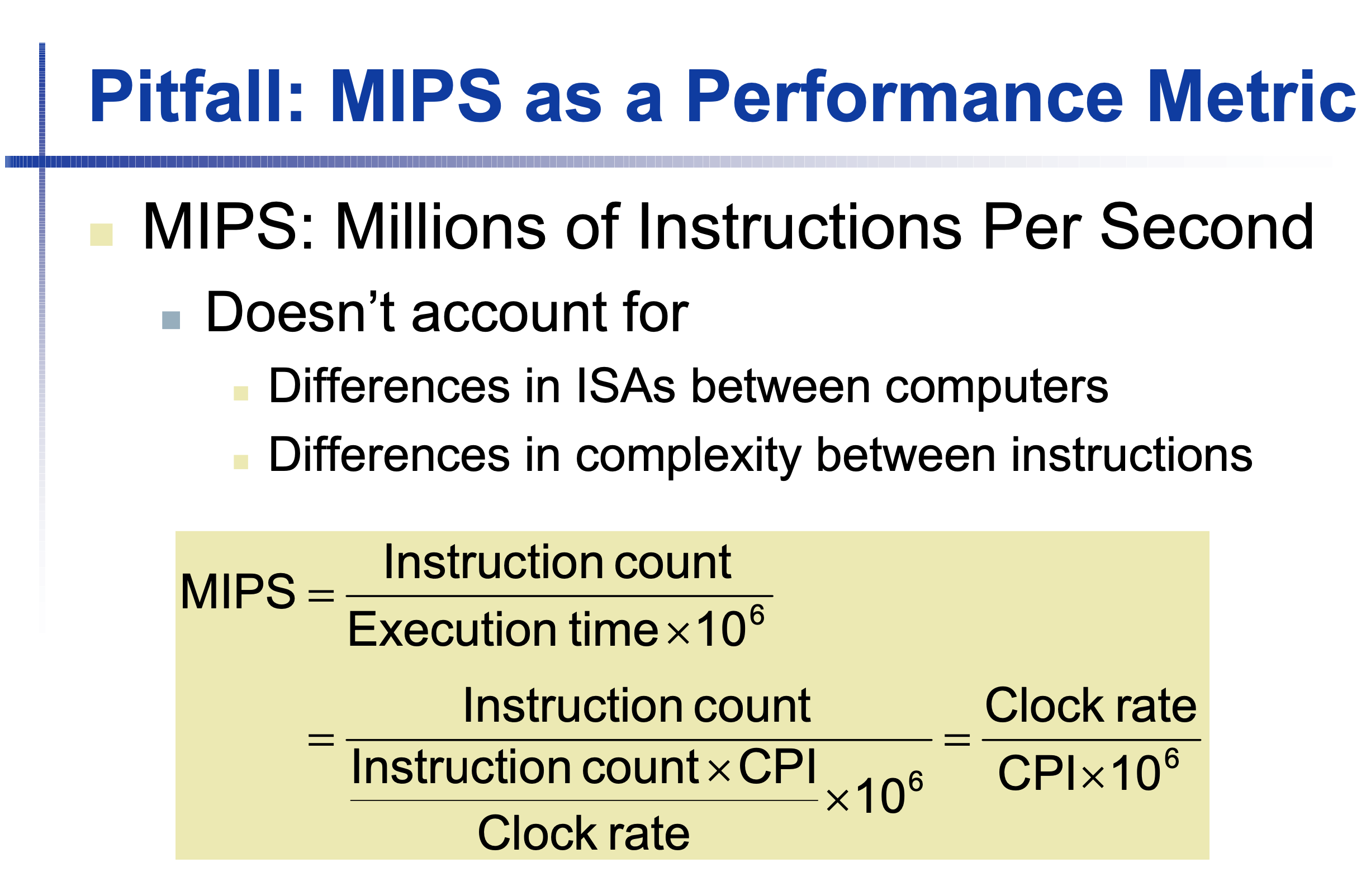
MIPS & IPS
IPS = (instructions / CPU_TIME) = clock_rate / CPI
MIPS = instructions / (execution_time * 10 ^ 6)
MIPS = (instructions) / ((instructions * CPI / clock_rate) * 10 ^ 6)
MIPS = clock_rate / (CPI * 10 ^ 6)
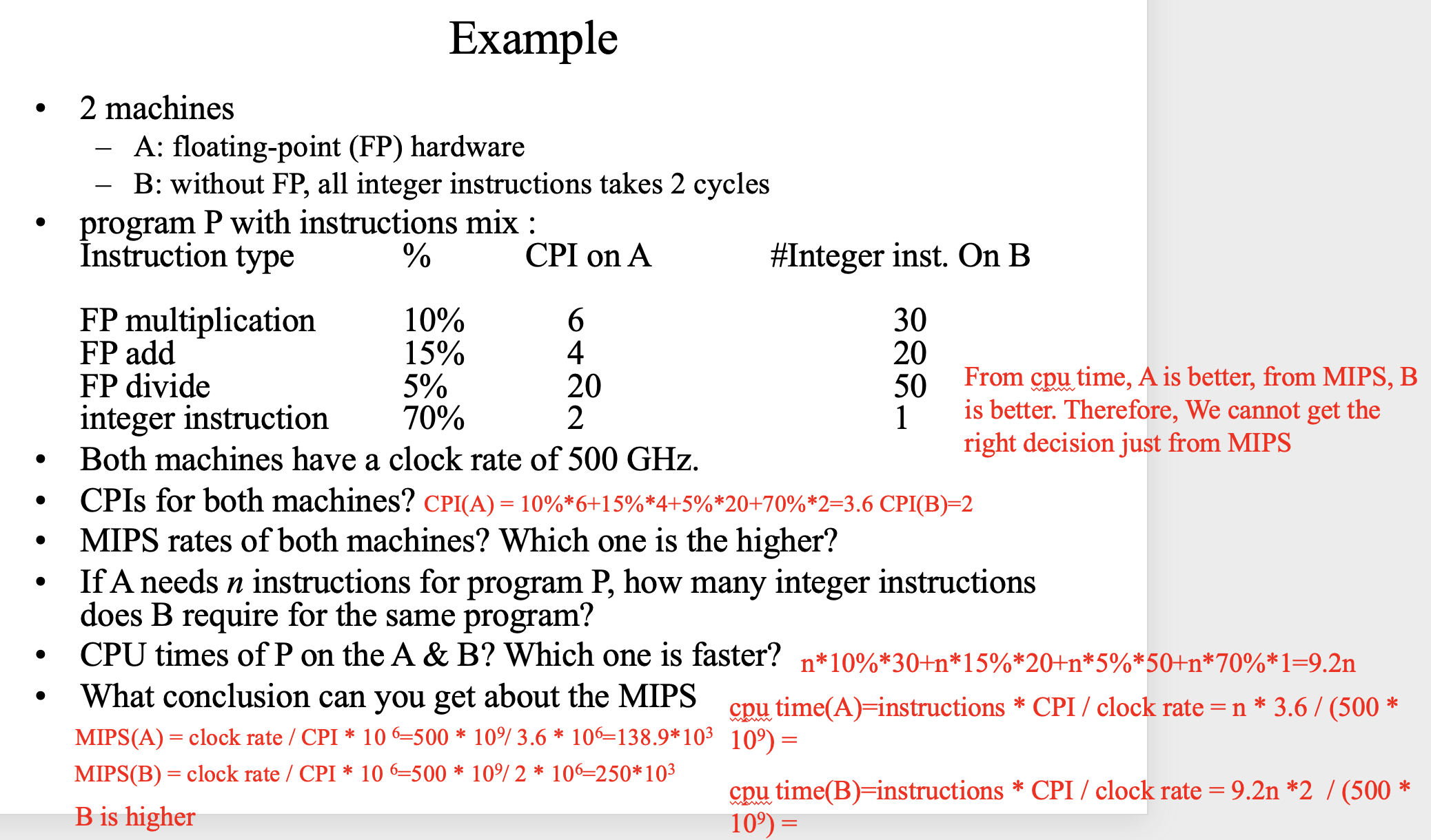
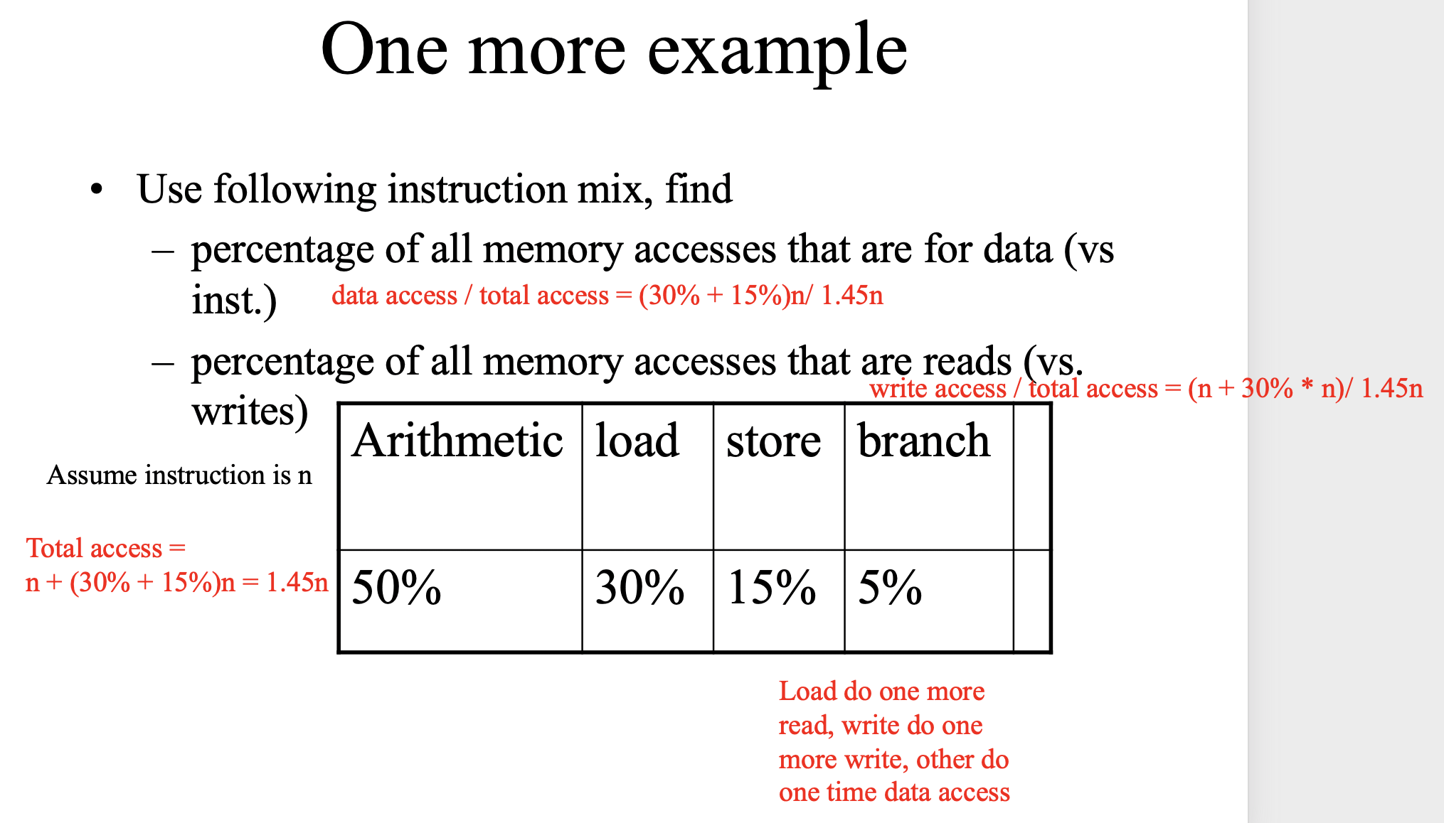
Example
Chapter 2
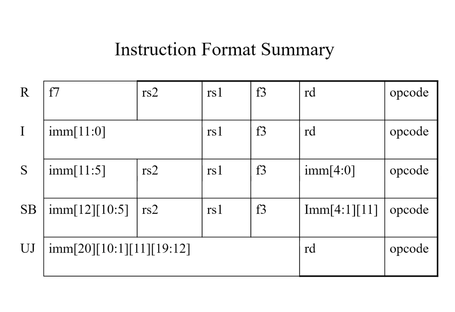
RISC-V Instruction
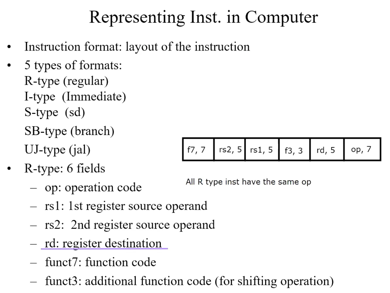
R-Type(regular)
add x9, x20, x21 => x9 = x20 + 21
| f7 | rs2 | rs1 | f3 | rd | op |
|---|---|---|---|---|---|
| 0(add) | 21 | 20 | 0 | 9 | 51(R) |
sub x1, x2, x3 => x1 = x2 - x3
| f7 | rs2 | rs1 | f3 | rd | op |
|---|---|---|---|---|---|
| 32(sub) | 3 | 2 | 0 | 1 | 51(R) |
I-type(Immediate)
Immediate field = funct7 + rs2 : 12 bits, holds a constant
ld x9 240(x22) => x9 = mem[x22 + 240]
| imm | rs1 | f3 | rd | op |
|---|---|---|---|---|
| 240 | 22 | 3 | 9 | 3(ld) |
addi X8, X9, 100 => x8 = x9 + 100
| imm | rs1 | f3 | rd | op |
|---|---|---|---|---|
| 100 | 9 | 3 | 8 | addi |
S-type(sd)
sd x1, 1000(x2) => mem(1000 + x2) = x1
| f7 | rs2 | rs1 | f3 | rd | op |
|---|---|---|---|---|---|
| 31 | 1 | 2 | 3 | 8 | 35(sd) |
1000 = 512+256+128+64+32+8 = 0011111(f7) 01000(rd)
SB-type(branch)
bne x10, x11, 2000. if x 10!= x11 take the branch
| f7 | rs2 | rs1 | f3 | rd | op |
|---|---|---|---|---|---|
0(1bit) 62(6bit) |
11 | 10 | 001 | 8(4bit) 0(1bit) |
103(bne) |
2000 = 0 111110 1000 0
UJ-type(jal)
jal x0 2000 => (1) x0 = PC + 4 (2) PC = PC + 2000
f7 + rs2 + rs1 + f3 = imm[20] + imm[10 : 1] + imm[11] + imm[19:12]
| f7 | rs2 | rs1 | f3 | rd | op |
|---|---|---|---|---|---|
| 0 | 1111101000 | 0 | 0 | 0 | 1101111(jal) |
2000 = 0 00000000 0 1111101000 0
Summary
Example
| Instruction | Format | f7 | rs2 | rs1 | f3 | rd | op |
| add x15, x16, x17 | R | add | 17 | 16 | 0 | 15 | R |
| sub x4, x5, x6 | R | sub | 6 | 5 | 0 | 4 | R |
| addi x8, x3, 20 | I | 20 | 3 | xxx | 8 | addi | |
| sd x17, 64(x21) | S | 2 | 17 | 21 | xxx | 0 | sd |
| ld x9, 8(x12) | I | 8 | 12 | xxx | 9 | ld | |
| beq x2, x3, 2000 | SB | xxx | 3 | 2 | xxx | xxx | beq |
| jal x16, 1000 | UJ | 1000 | 16 | jal | |||
| addi x21, x23, 8 | I | 8 | 23 | xxx | 21 | addi | |
Addressing Mode
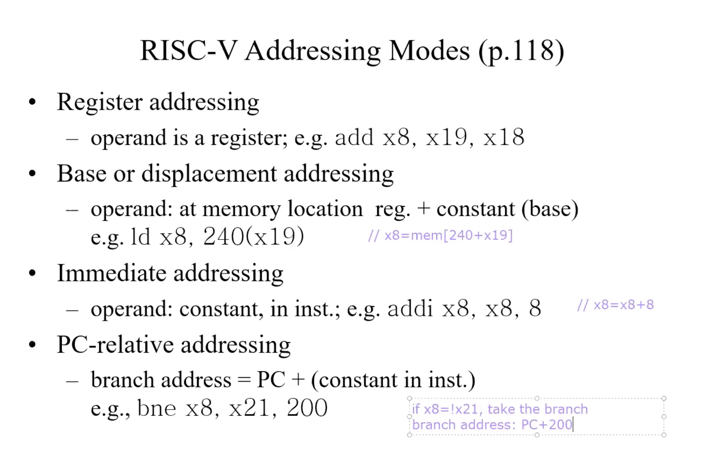
Branch address
beq x1, x2, offset => if (x1 = x2) goto brach address
Format of brach address:- Offset in binary, 13 bits:imm[12:0]
- Replace the least significant bit by 0(least significant bit is the most right bit)
- Branch address = PC + imm[12:0]0(add one more zero in the right, the total length is 14)
Example
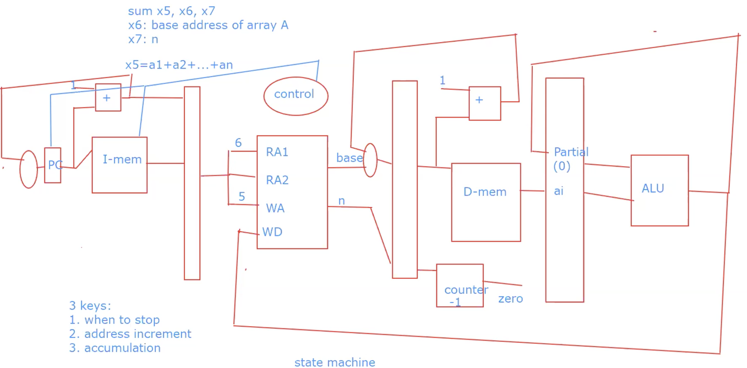
Chapter 4
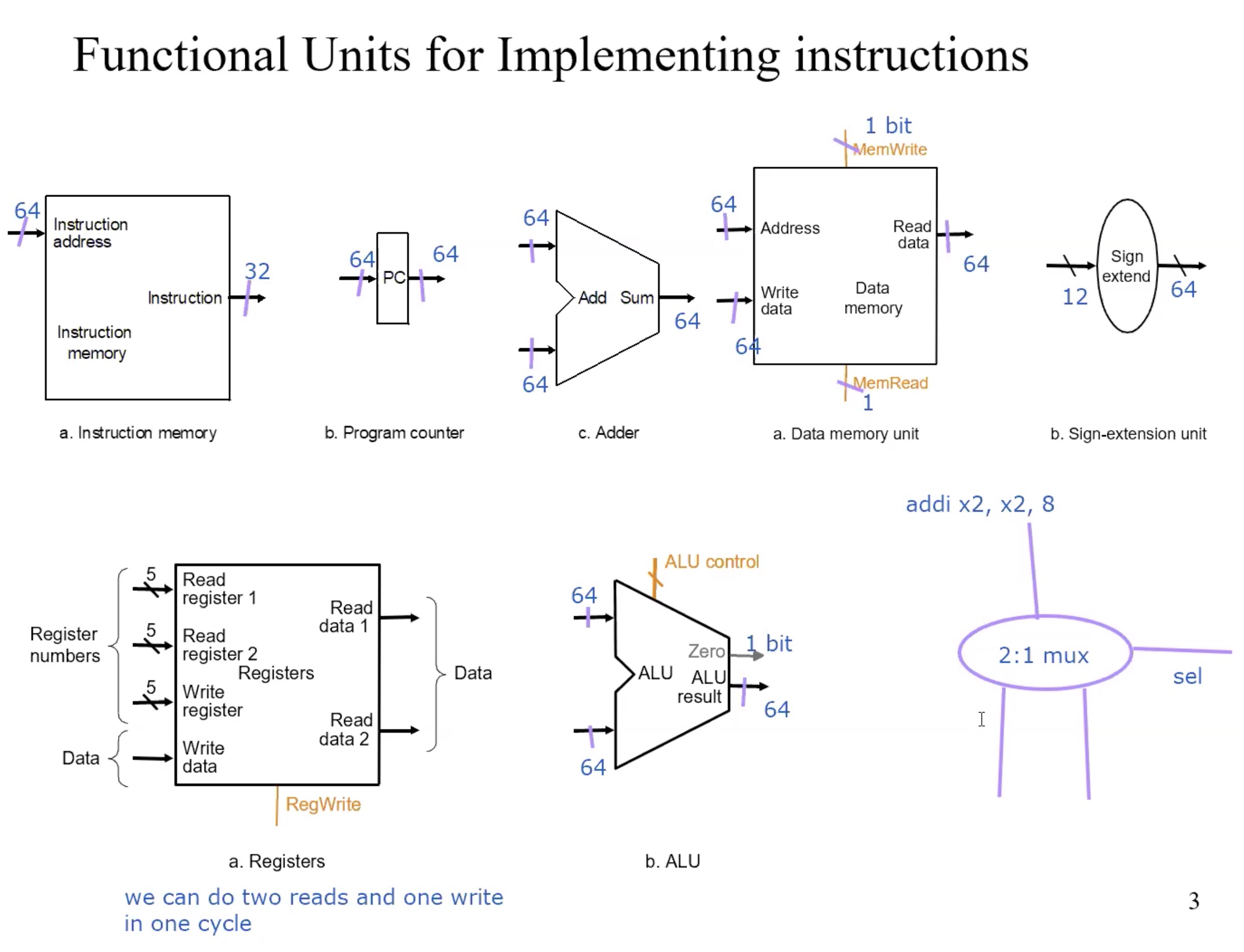
functional units
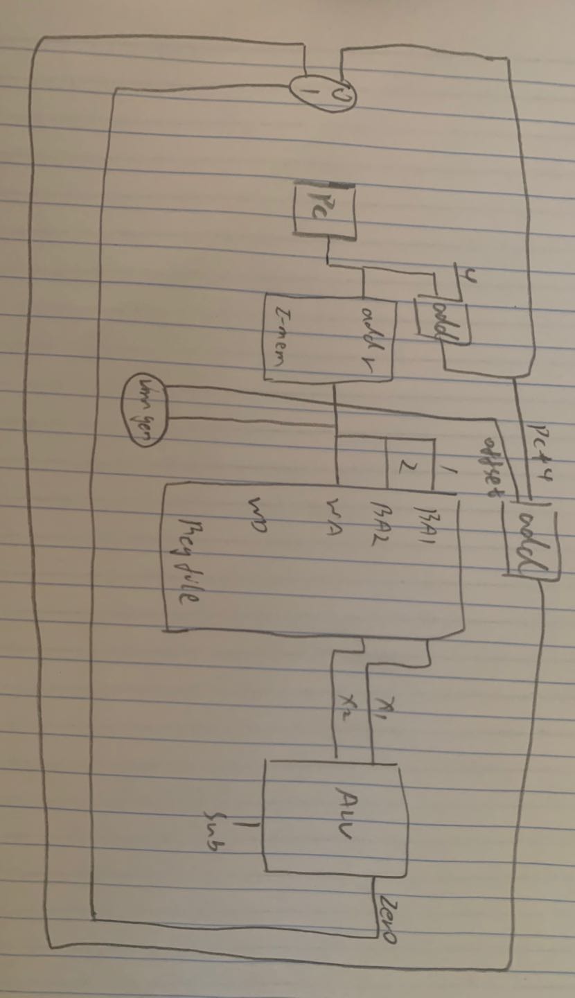
DataPath
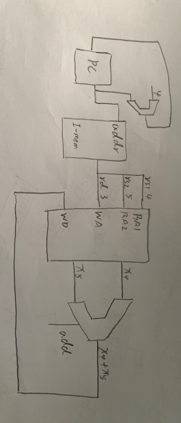
R-type
Basic Steps
- fetch instructions
- select registers(rs1, rs2)
- ALU operations on two data, need ALU
- write back registers
Example
add x3, x4, x5 => x3 = x4 + x5
| f7 | rs2 | rs1 | f3 | rd | op |
|---|---|---|---|---|---|
| add | 5 | 4 | 0 | 3 | R |
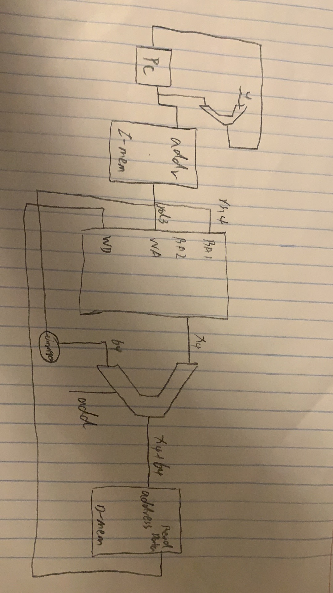
I-type(Immediate)
Basic Steps
- fetch instructions
- select registers(rs1)
- calculate address, need ALU
- access memory(read memory)
- write register file(rd)
Example
ld x3 64(x4) => x3 = mem[x4 + 64]
| imm | rs1 | f3 | rd | op |
|---|---|---|---|---|
| 64 | 4 | xxx | 3 | addi |
 |
S-type(sd)
Basic Steps
- fetch instructions
- select two register(rs1, rs2)
- calculate address, need ALU
- access memory(write memory)
Example
sd x3 64(x4) => mem[x4 + 64] = x3
| f7 | rs2 | rs1 | f3 | rd | op |
|---|---|---|---|---|---|
| 2 | 3 | 4 | xxx | 0 | sd |
 |
SB-type(branch)
Basic Steps
- fetch instructions
- select registers
- test condition, calculate branch address(need additional ALU)
Example
beq x1, x2, offset => if x1 = x2, pc = offset + pc + 4
| f7 | rs2 | rs1 | f3 | rd | op |
|---|---|---|---|---|---|
| xxx | 2 | 1 | xxx | xxx | beq |
UJ-type(jal)
Example
jal x0 2000 => (1) x0 = PC + 4 (2) PC = PC + 2000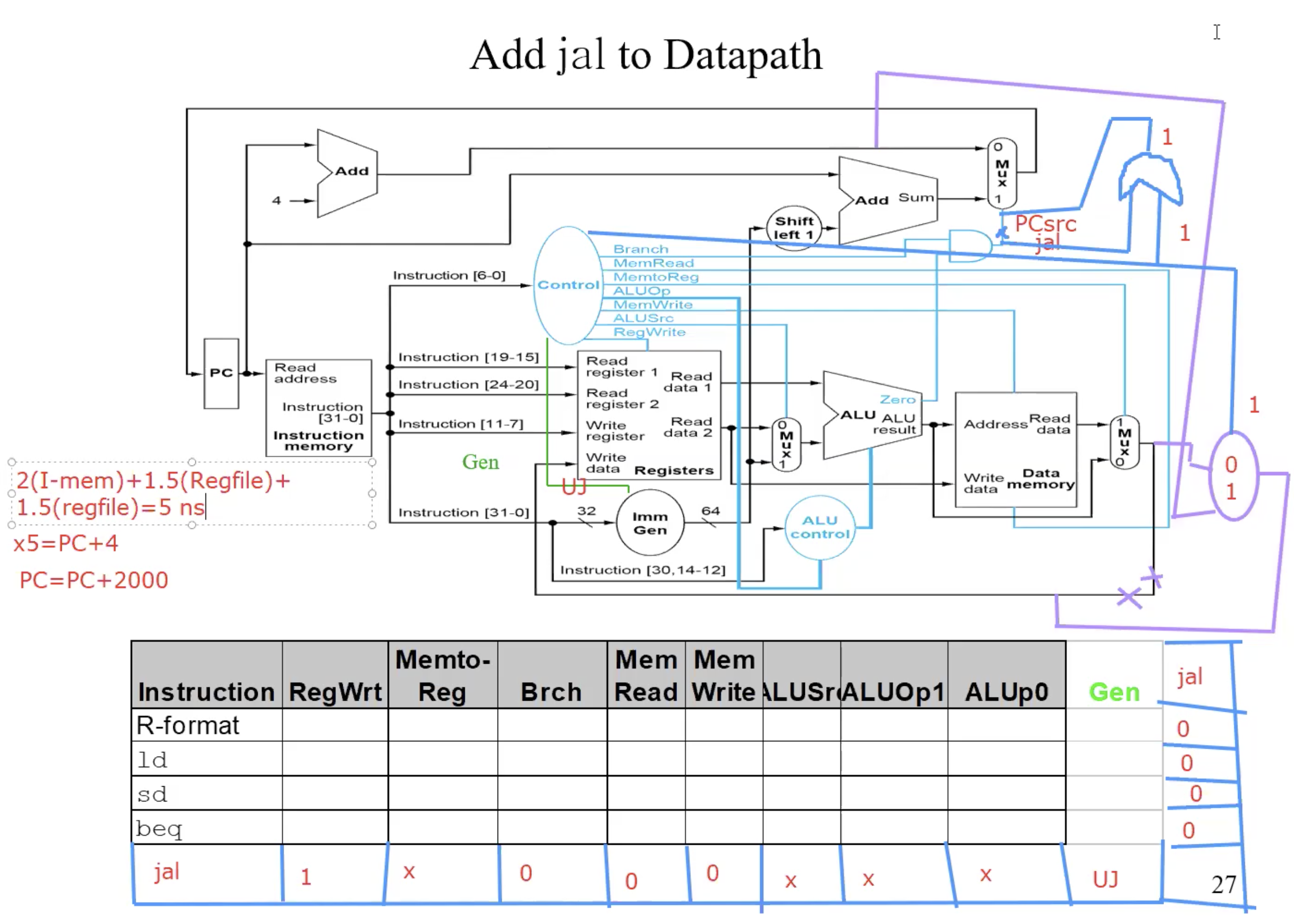
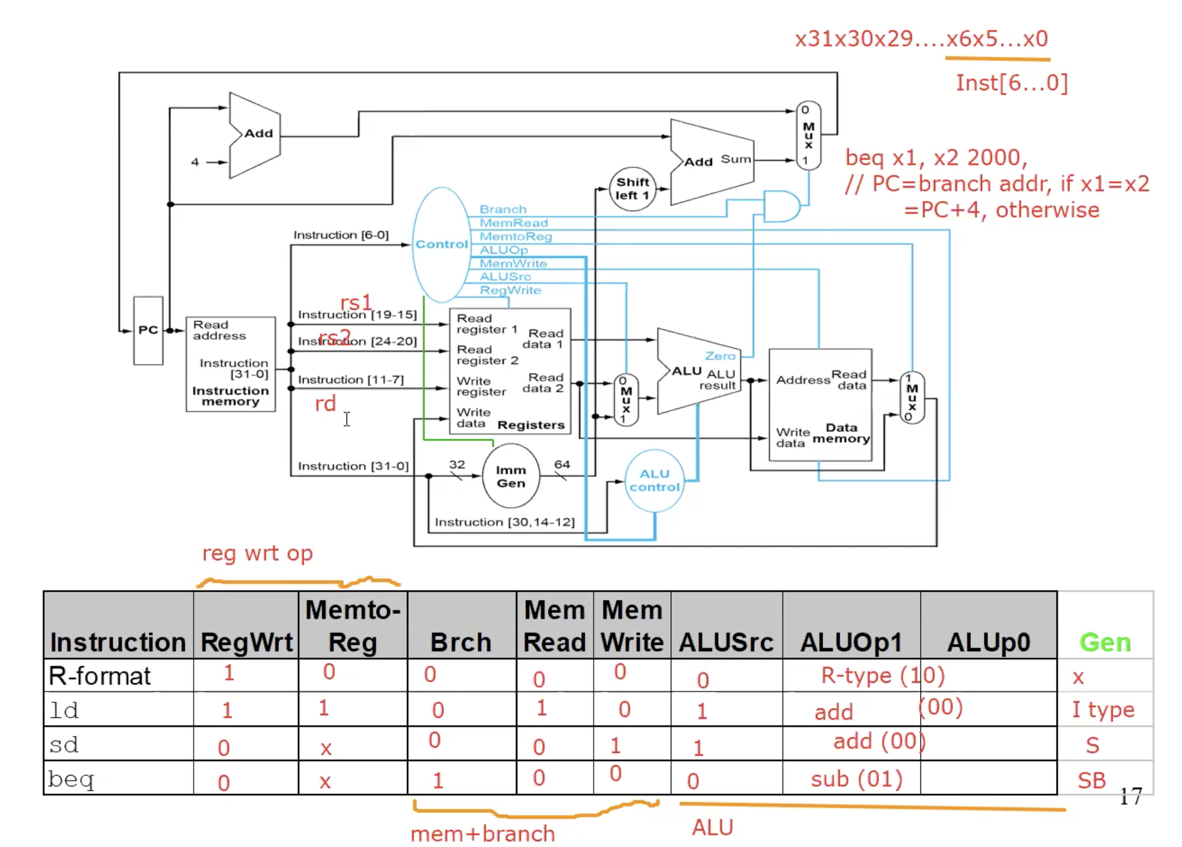
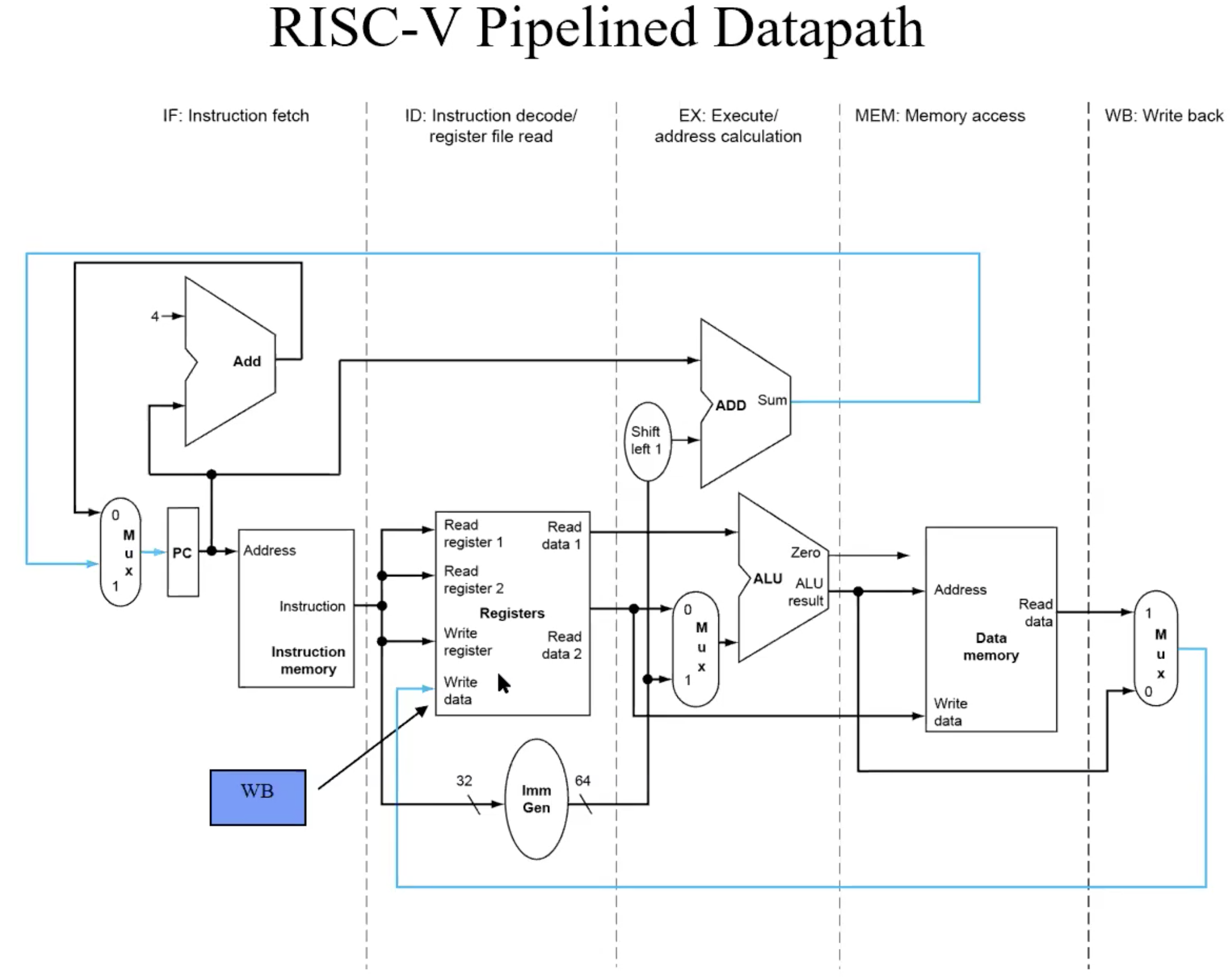
Single Datapath for Single Cycle
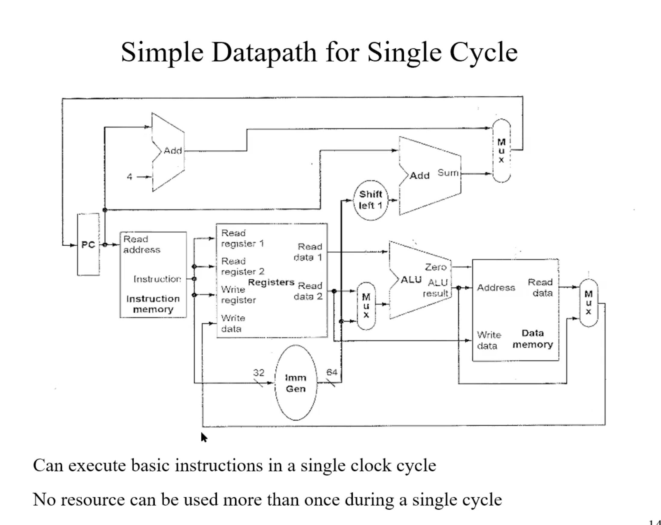
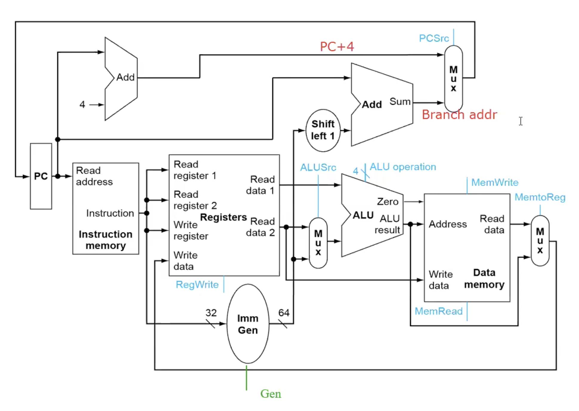
Summary
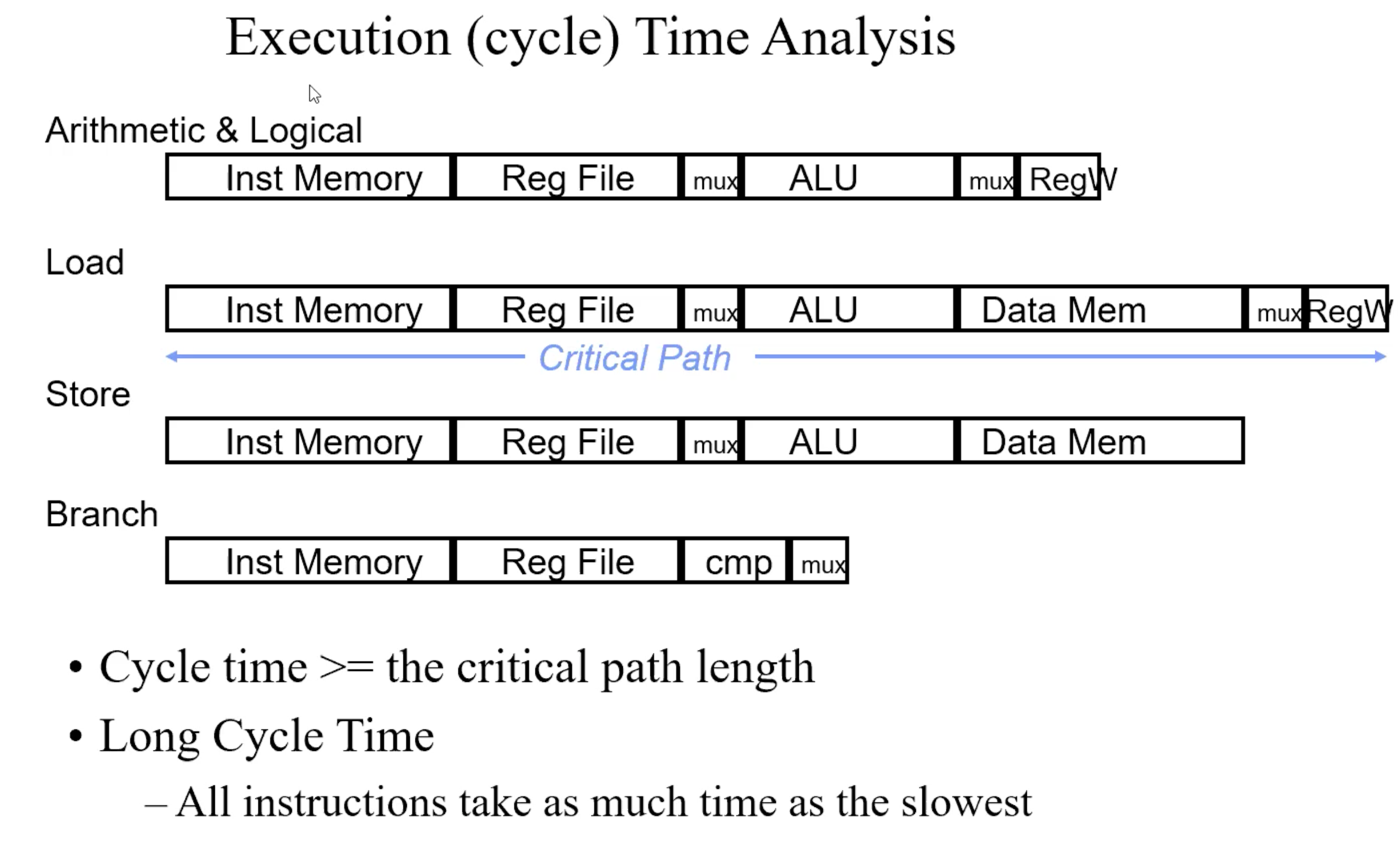
Data Memory is only used during load and store.
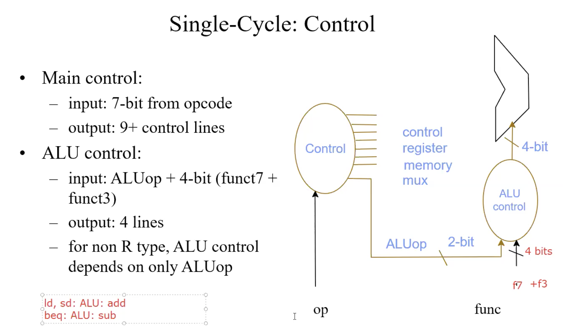
Function code of ALU Control
ALU used for
- Load/Store: F = add
- Branch: F = subtract
- R-type: F depends on f7,f3
| ALU control | Function |
|---|---|
| 0000 | AND |
| 0001 | OR |
| 0010 | add |
| 0110 | subtract |
truth table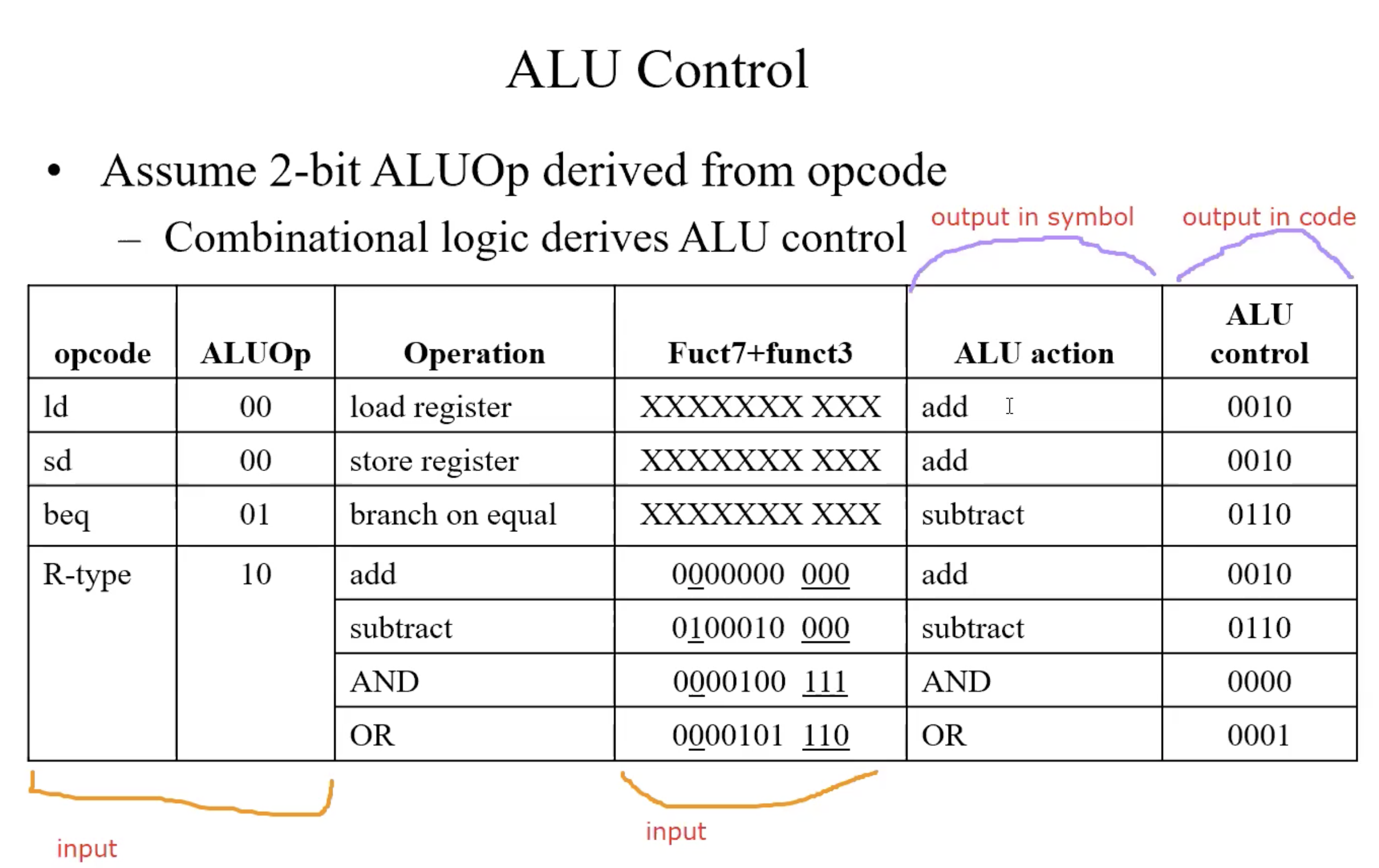
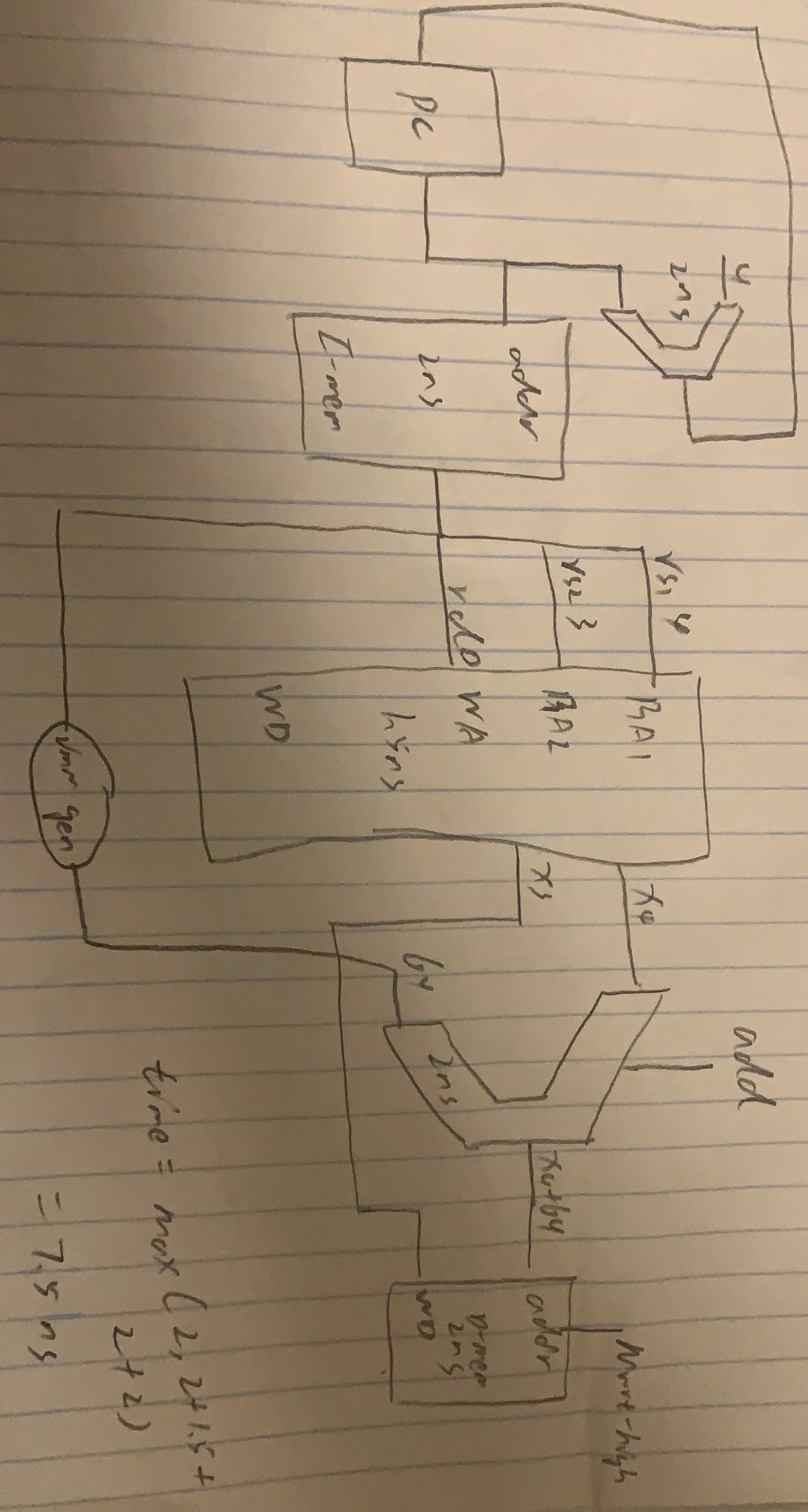
Summary of execution Time Analysis
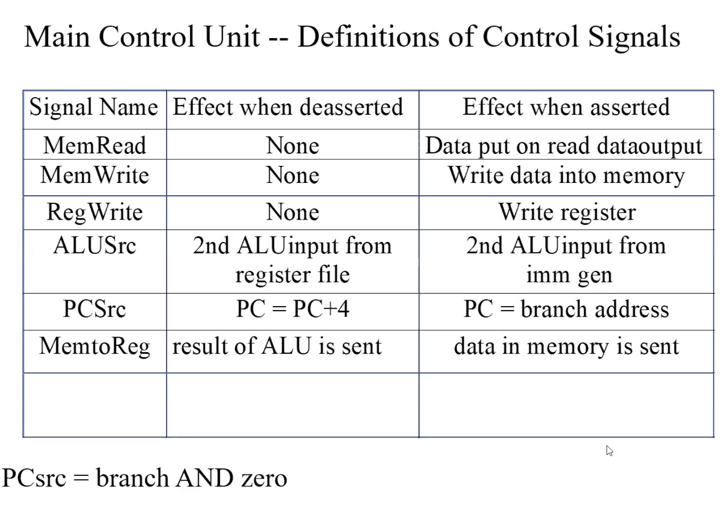
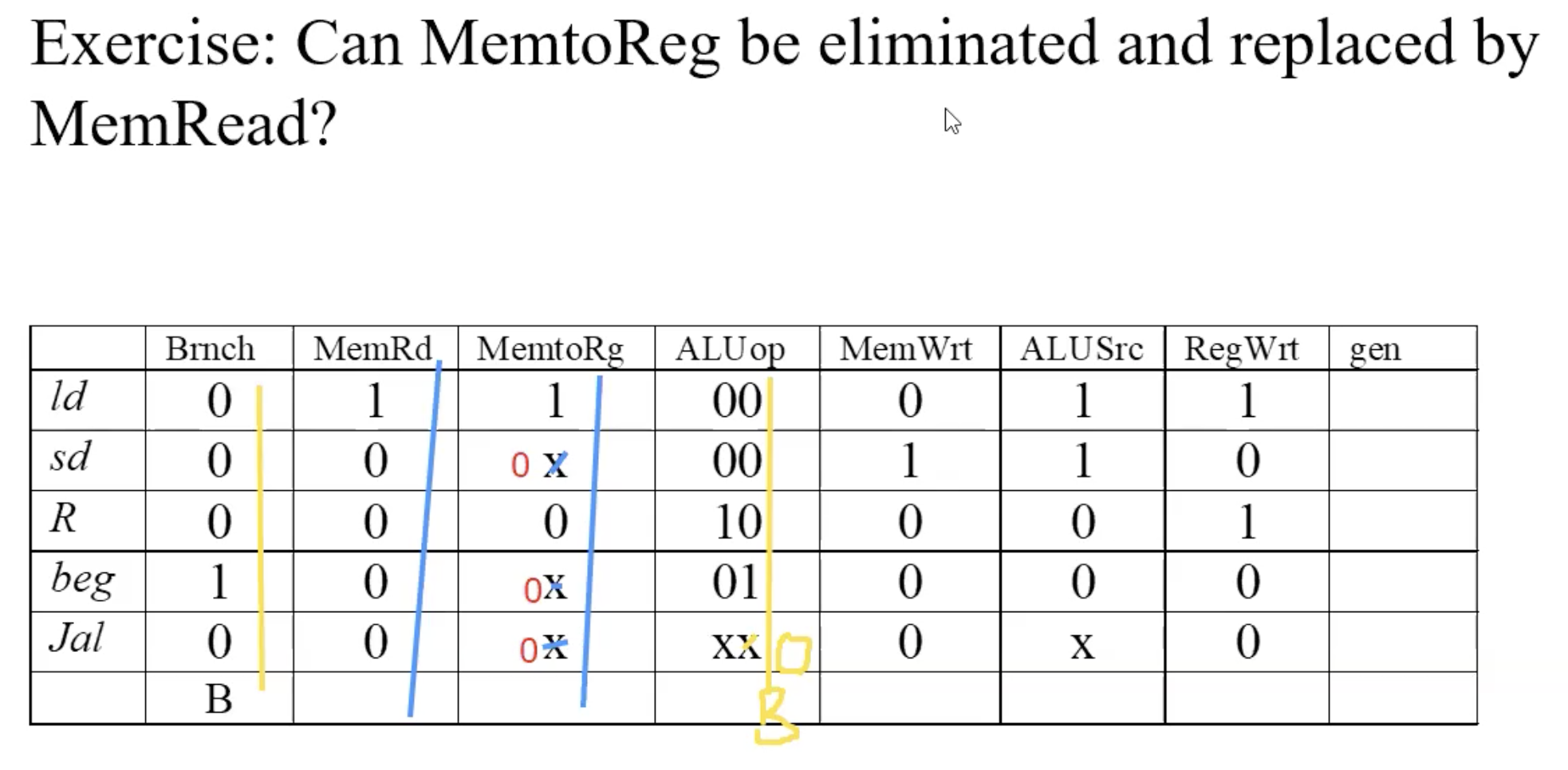
optimization(replace & eliminated control line)
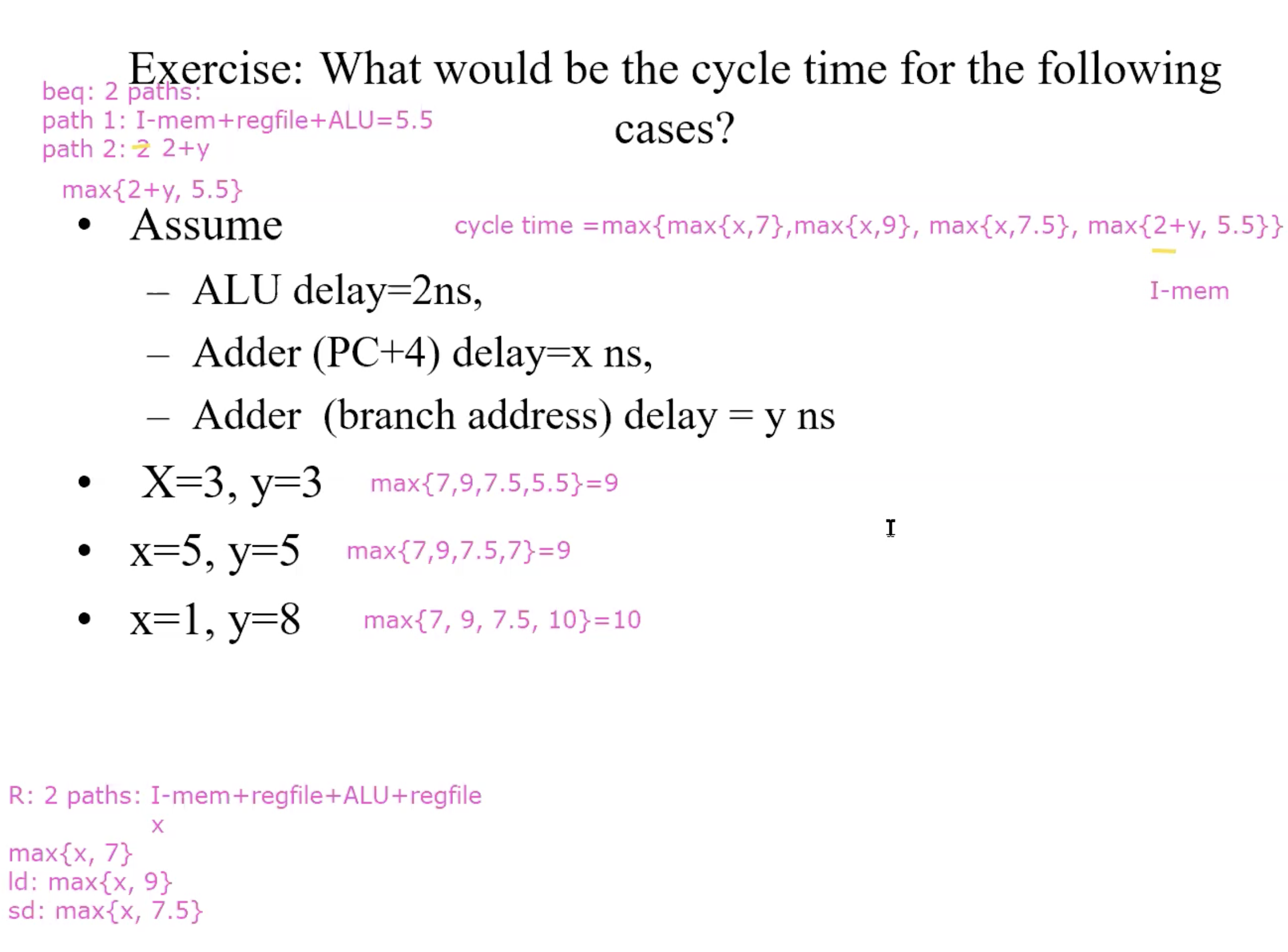
cycle time example
PipeLine
Basic idea of pipeline
5 steps: IF(instruction fetch), ID(Instruction decoding), EX(execution), MEM(memory access), WB(write back).
For the current step, hardware of other steps are idle.
Use the idle hardware to work on other instructions
Overlap the instructions executions
Add buffers to hold partial results of instruction executions
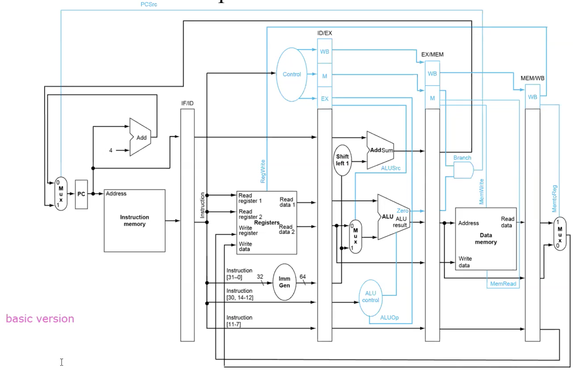
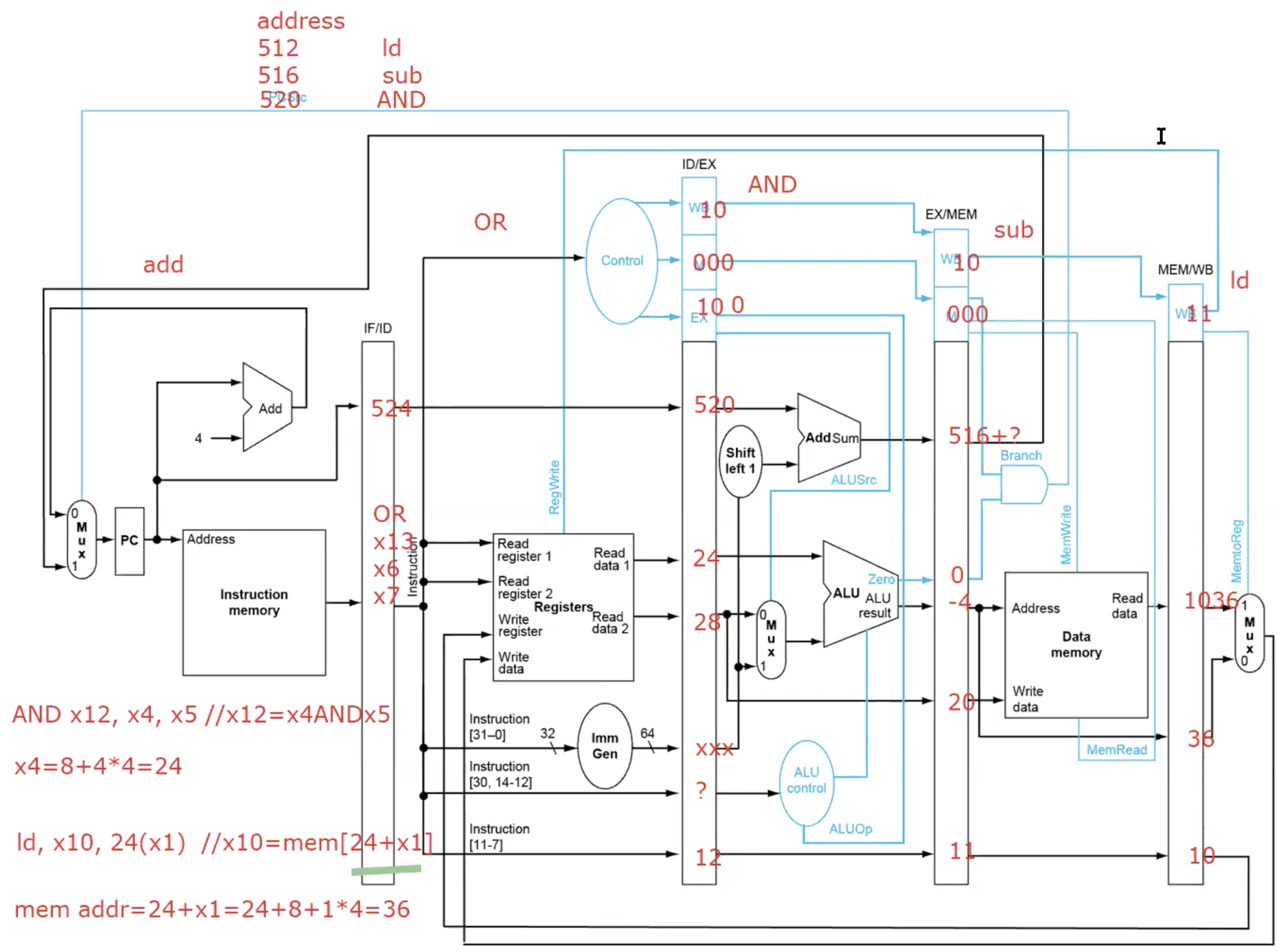
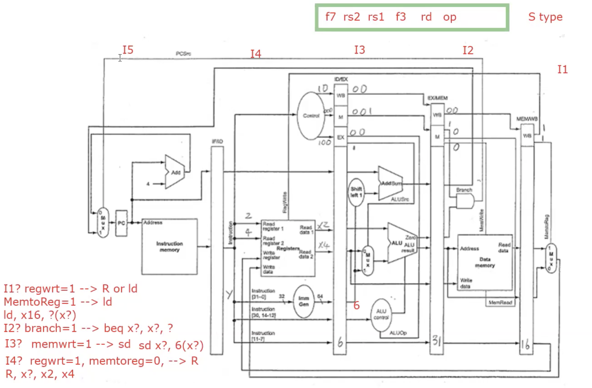
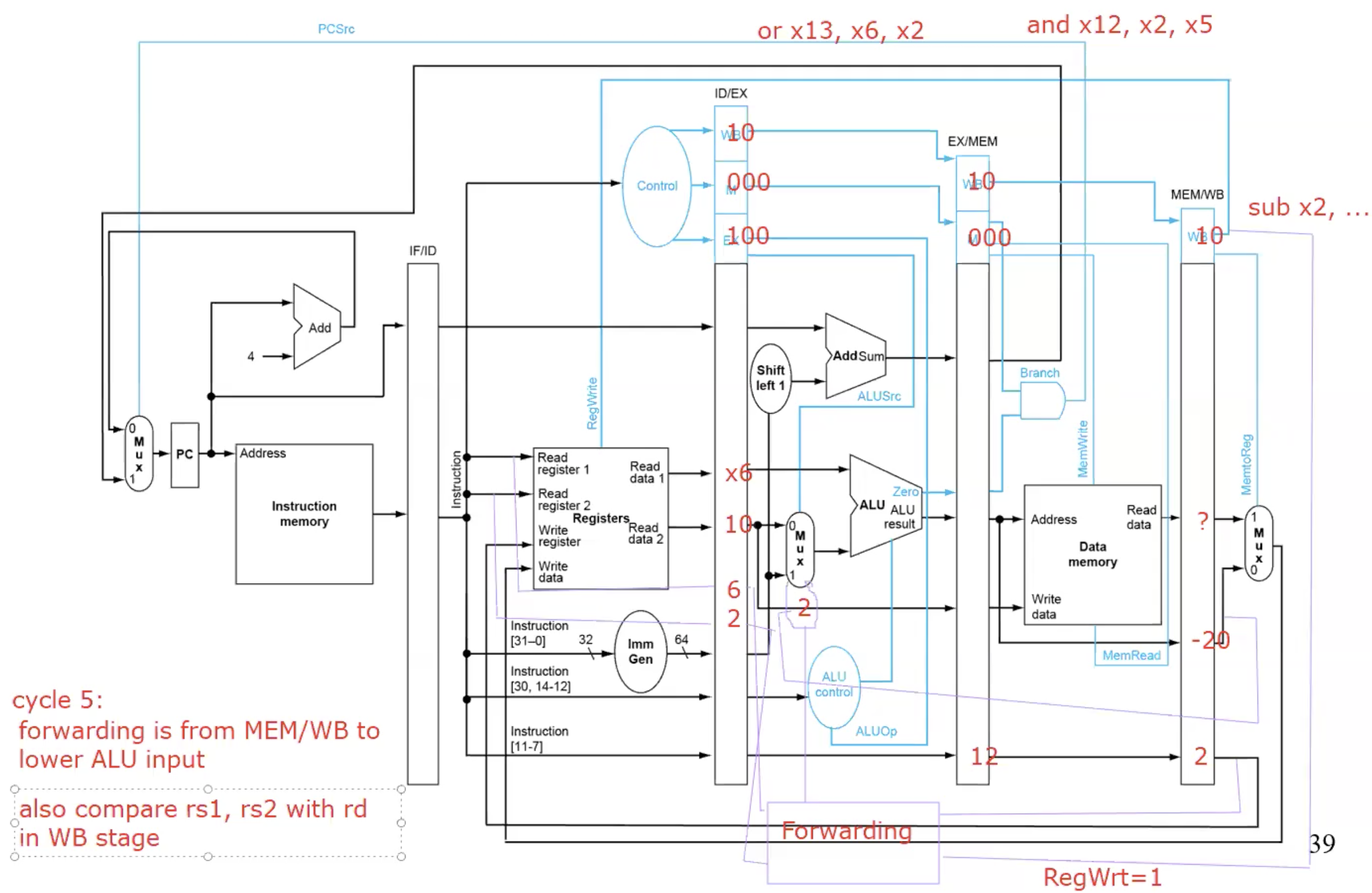
RISC-V Pipelined Datapath
Pipeline Control
Example add x4, x2, x3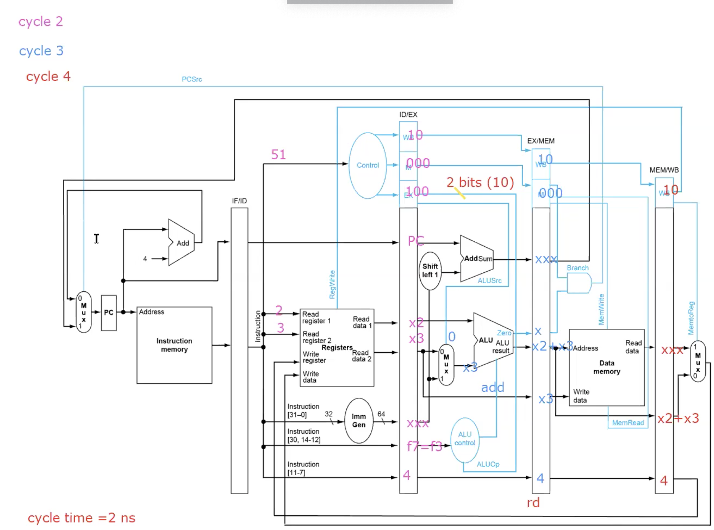
- Execution time of n instructions
5 + n - 1 = n + 4, the first instruction is 5 cycle time, the remaining instruciton is 1 cycle time.
- Speedup
(5 * n) / (n + 4) ≈ 5
- CPI = cycle time / instruction = (n + 4) / n ≈ 1
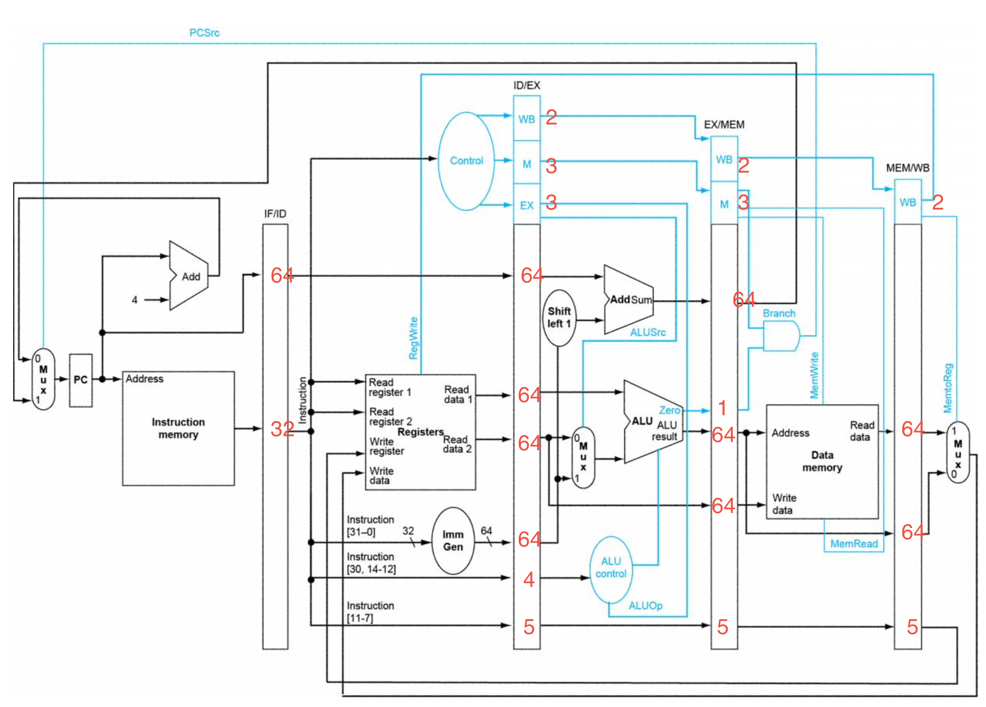
Buffer size
- IF/ID: 32(inst) + 64(PC) = 96
- ID/EX: 2+3+3+64*4+4+5 = 273
- EX/MEM: 2+3+1+64*3+5 = 203
- MEM/WB: 2+5+64*2 = 135
Example: How the five instructions go through the pipe, and what are the buffer values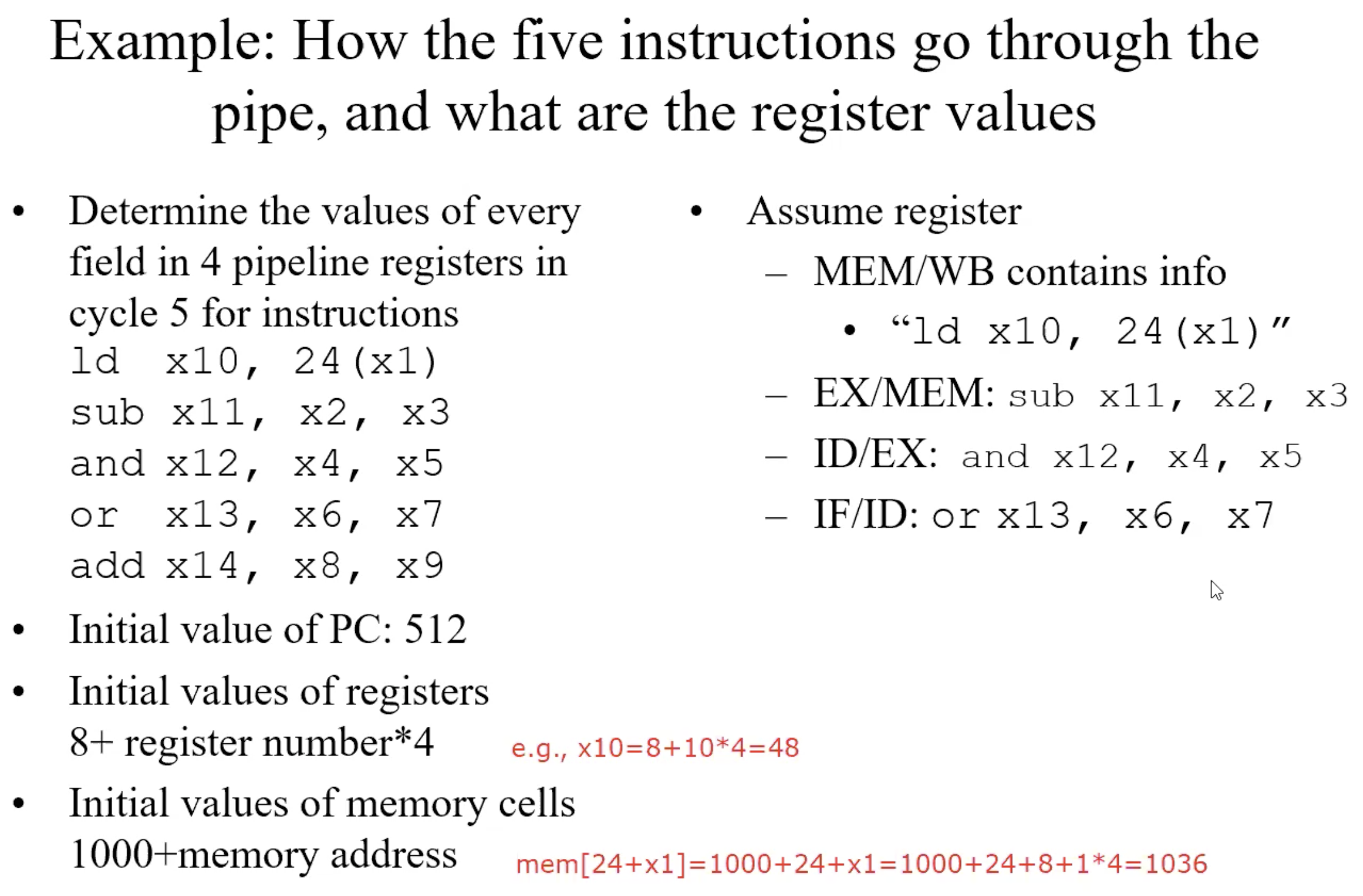
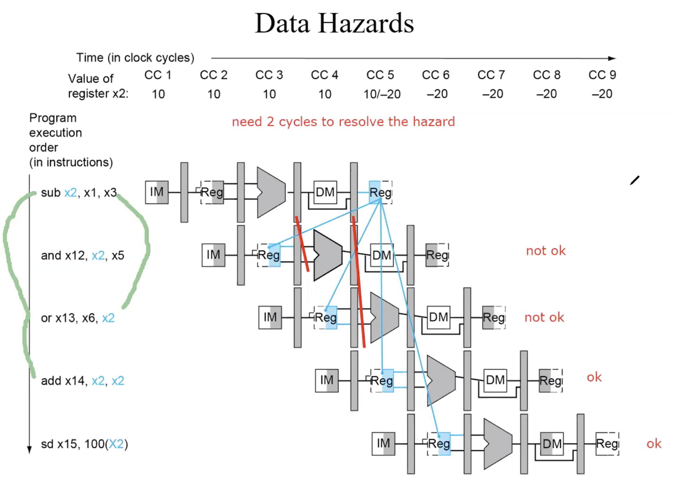
Data Hazards

WAW,WAR won’t cause Data Hazards, because write is the last process of instruction, write always after the read.
Handle Data Hazards
Compiler approach
insert dummy operations or “nops”
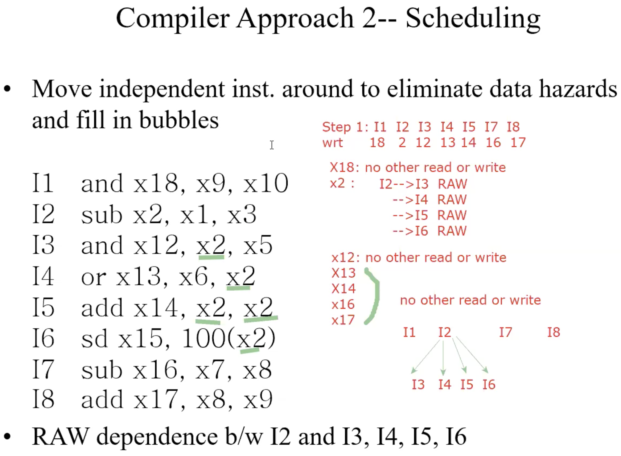
reschedule instructionsHardware approach
forwarding
Example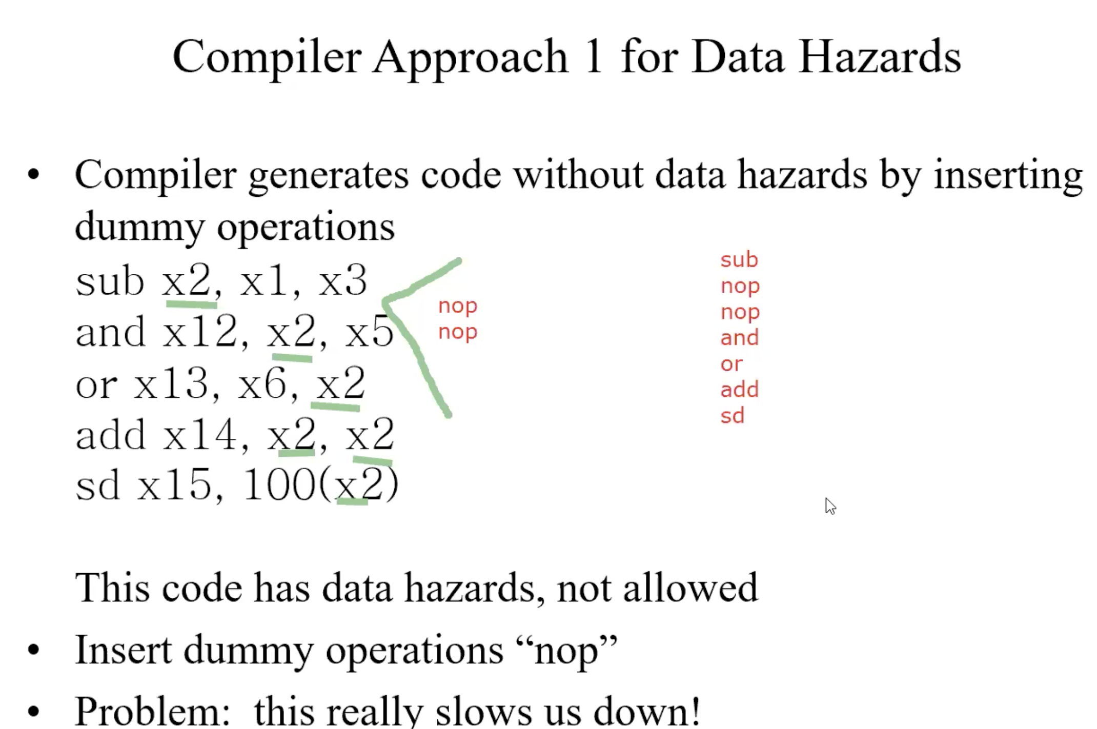
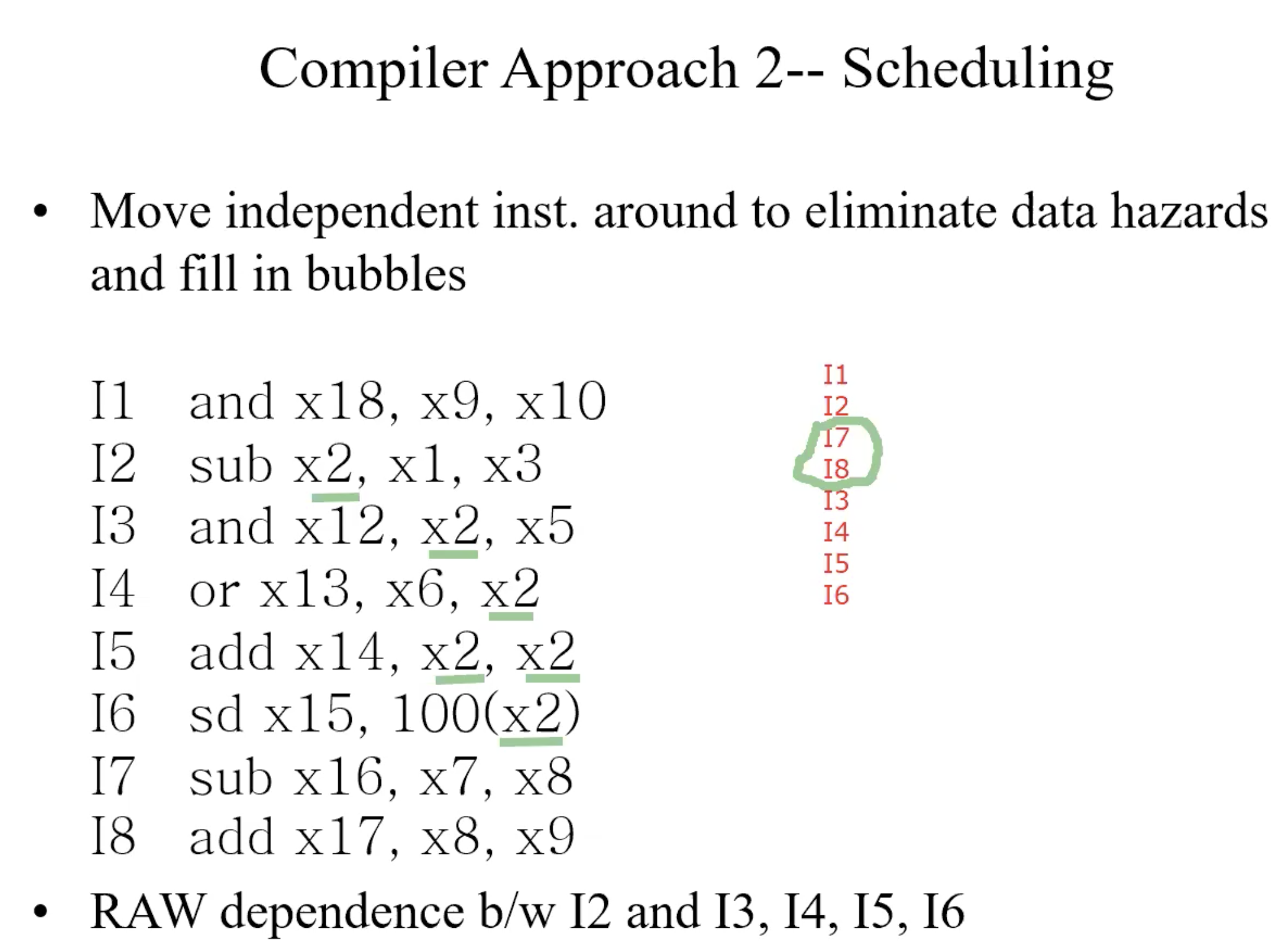
How to identify all dependence
- Find all instructions that write registers
- For each such instruction writing register xj, identify all other instructions that either read or write register xj
- Data dependence graph(DDG)
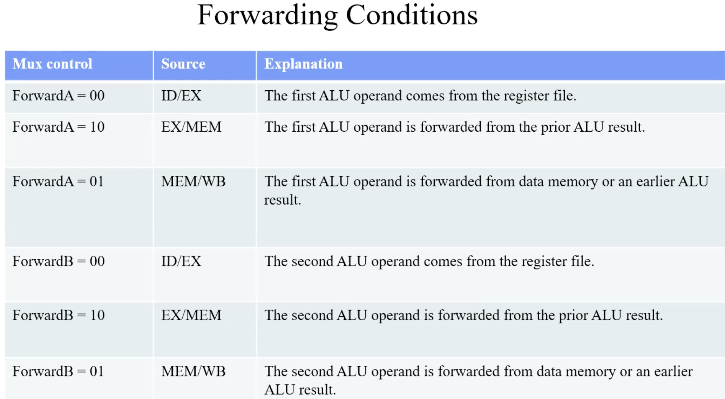
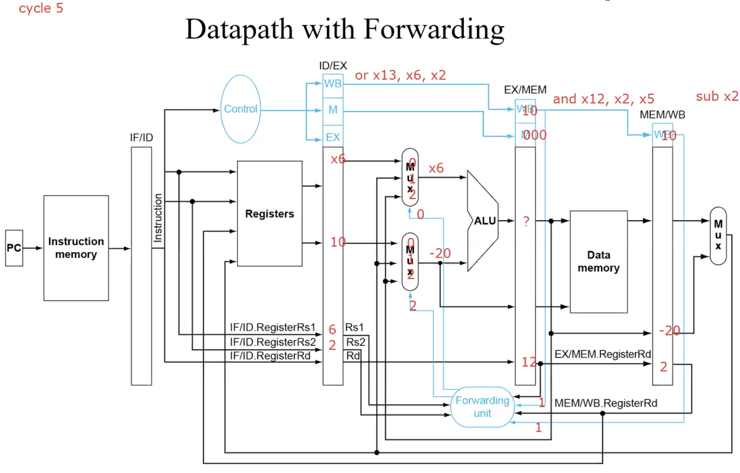
Forwarding
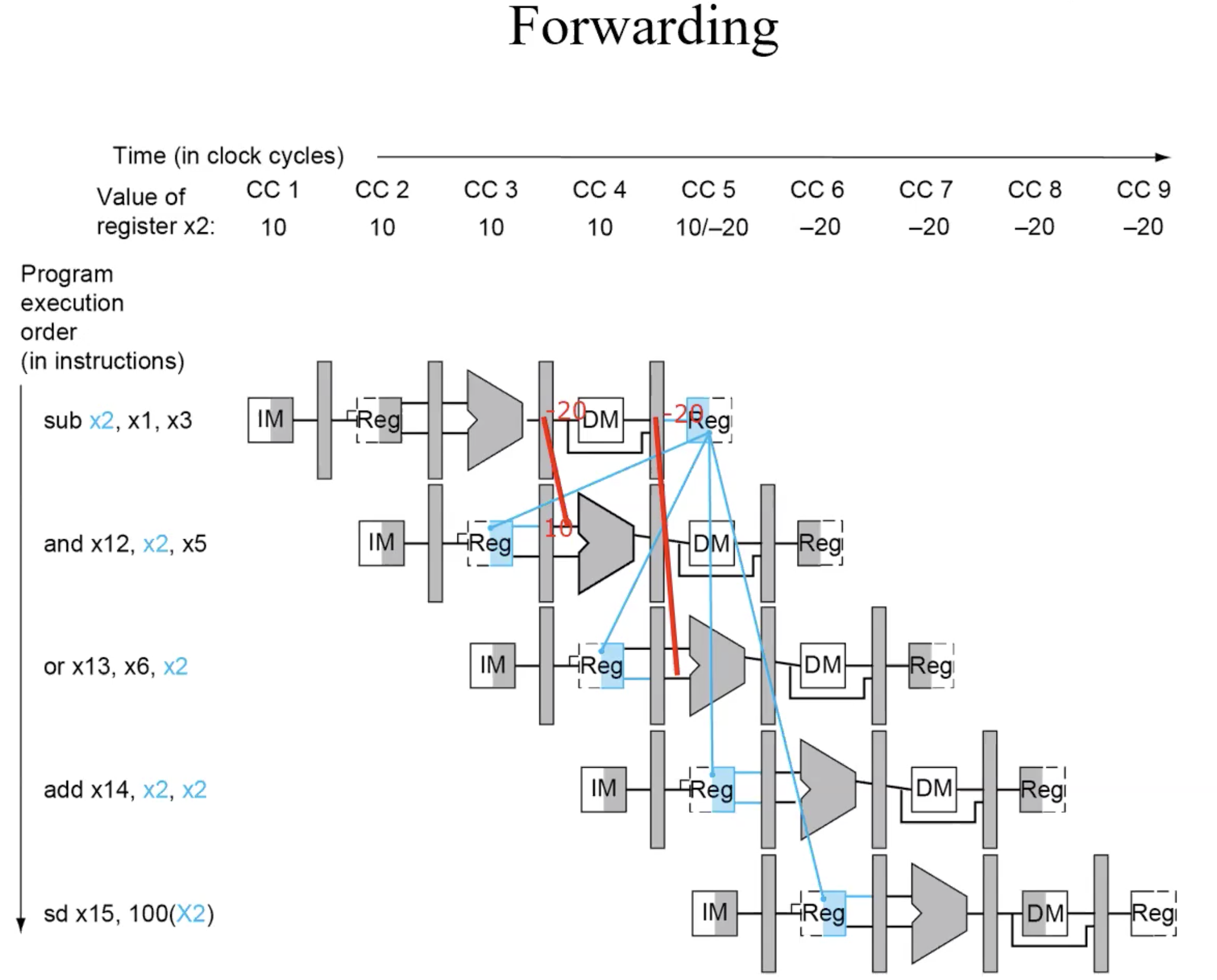
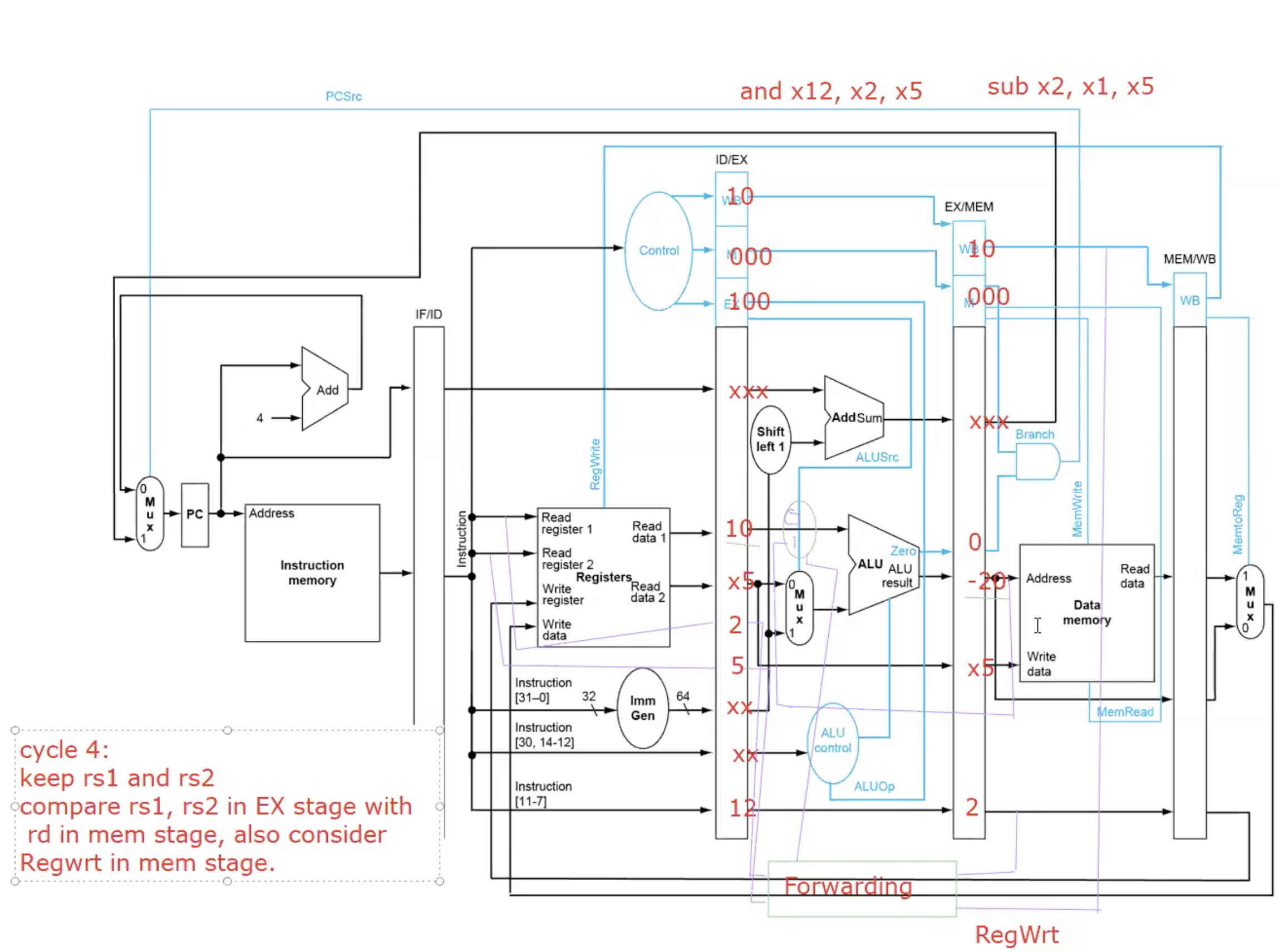
basic forwarding path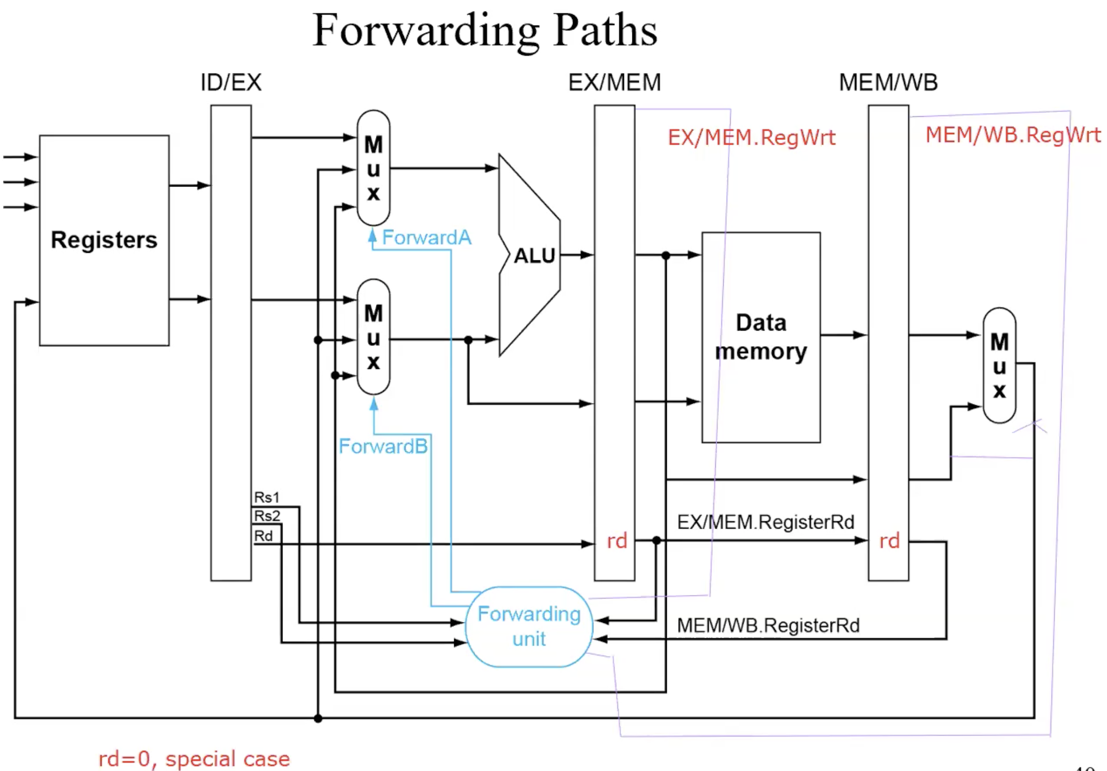
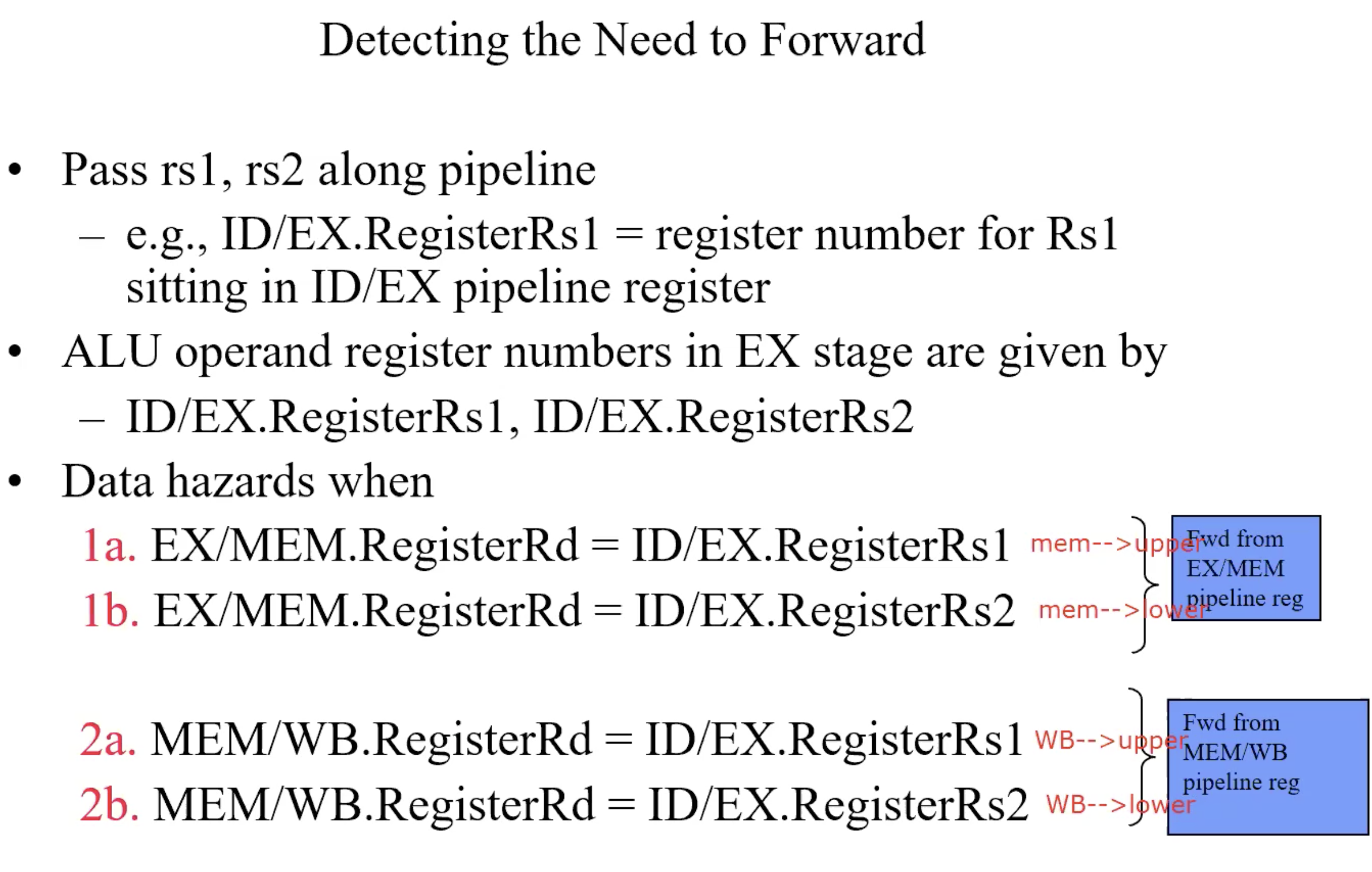
Detecting the need to Forward
But only if forwarding instructions will write to a register!
EX/MEM.RegWrite, MEM/WB.RegWrite
Only if Rd for that instruction is not 0
EX/MEM.RegisterRd!=0
MEM/WB.RegisterRd!=0
summary-forwarding conditions
A Bug: Double Data Hazard
Consider the sequence:
add x1, x1, x2
add x1, x1, x3
add x1, x1, x4Both hazards occur
Want to use the most recent
Revise MEM hazard condition
Only forward if EX hazard condition isn’t true
Load-use Hazard, can’t forward
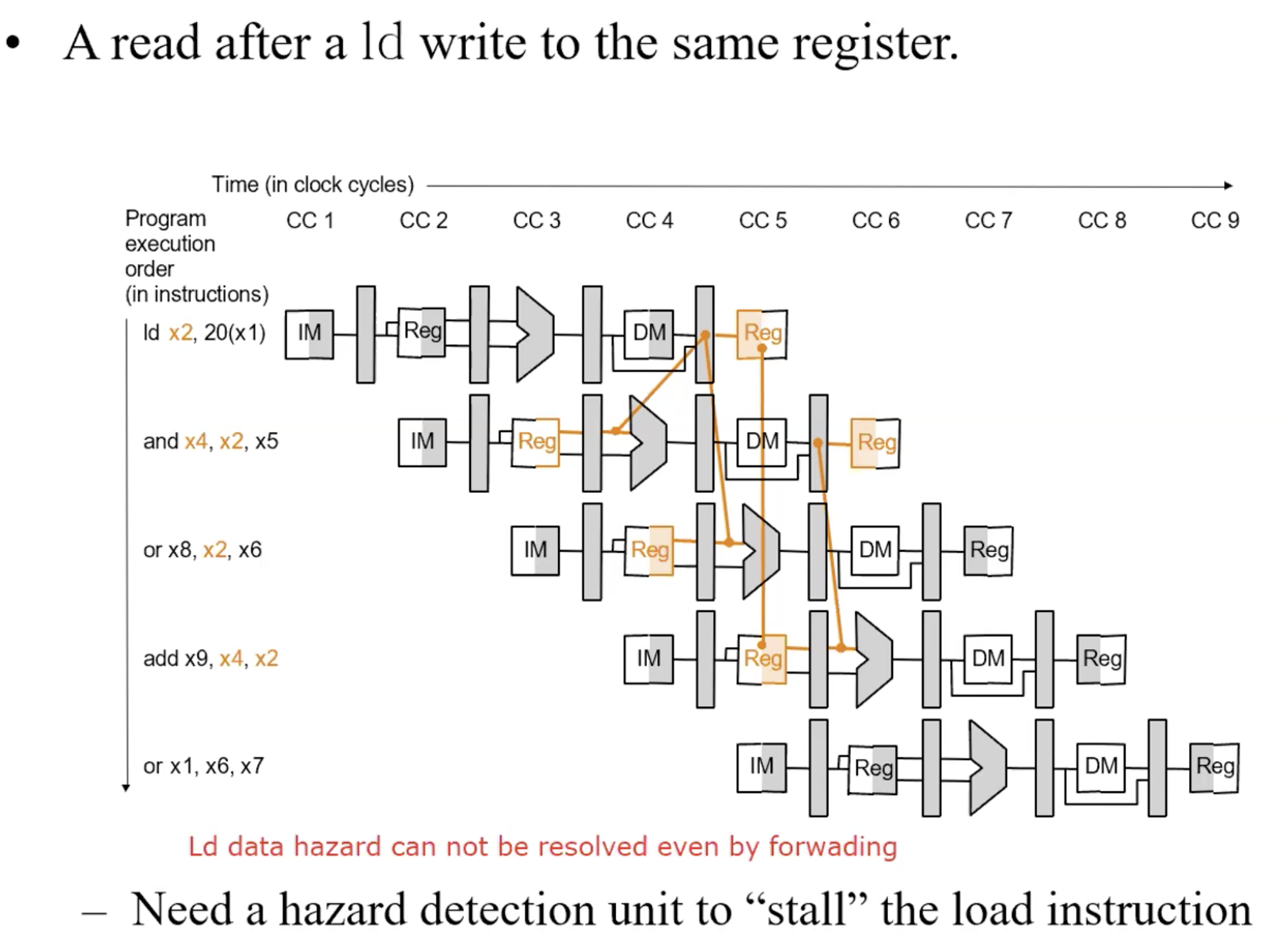
Harzard Detection
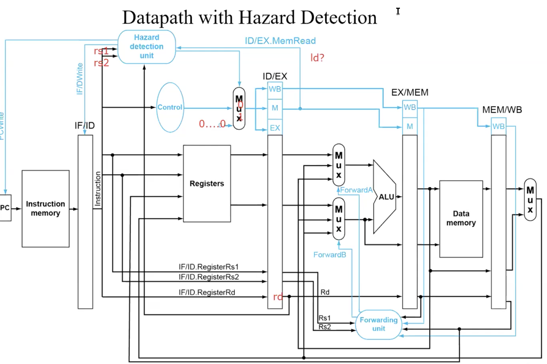
check if instruction x1 in EX and instruction in ID have Load Harzard.
ALU operand register numbers in ID stage are given by
IF/ID.RegisterRs1, IF/ID.RegisterRs2
Load-use harzard when
ID/EX.MemRead and
((ID/EX.RegisterRd = IF/ID.RegisterRs1) or
(ID/EX.RegisterRd = IF/ID.RegisterRs2))if detected, stall and insert bubble
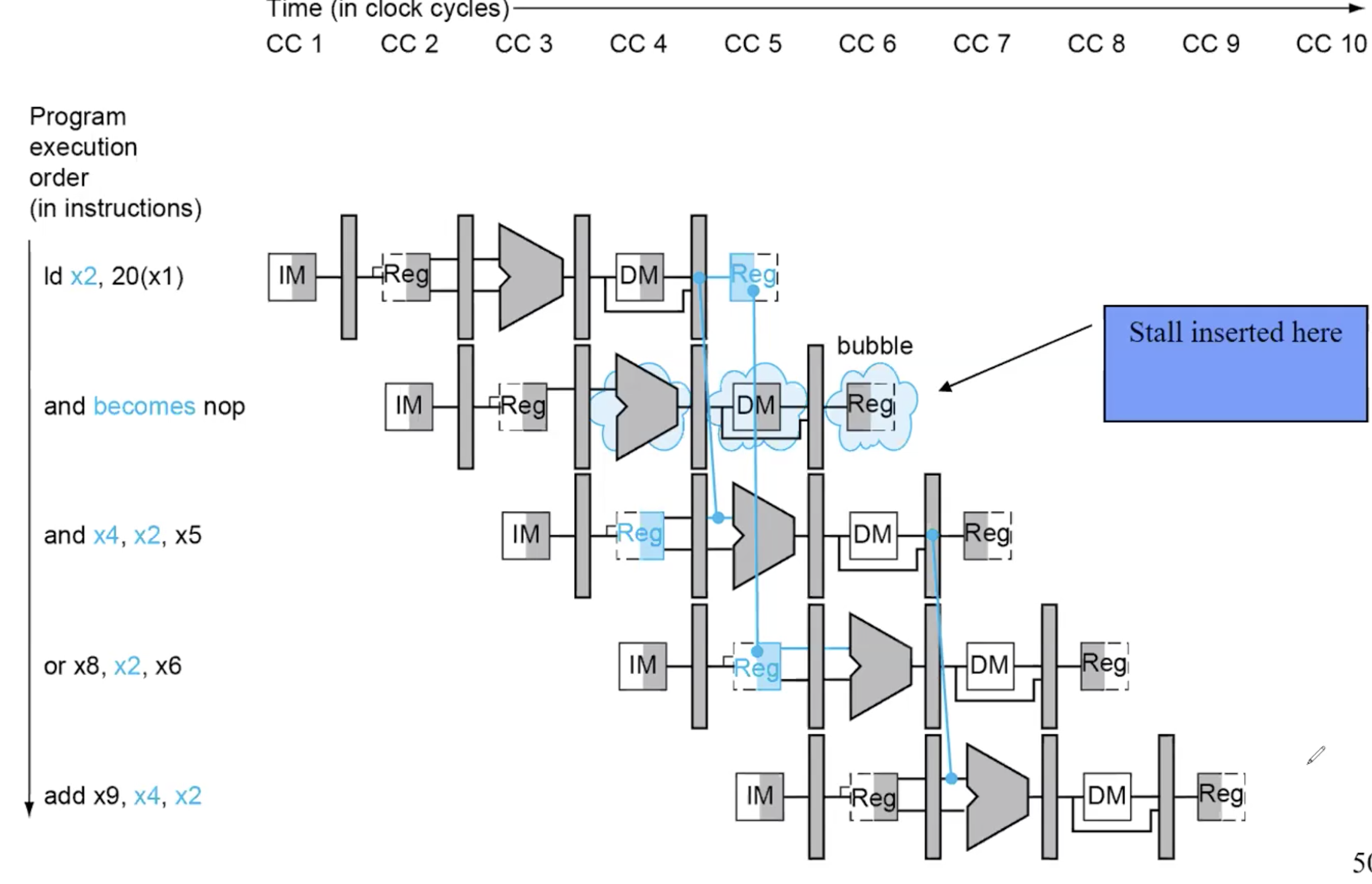
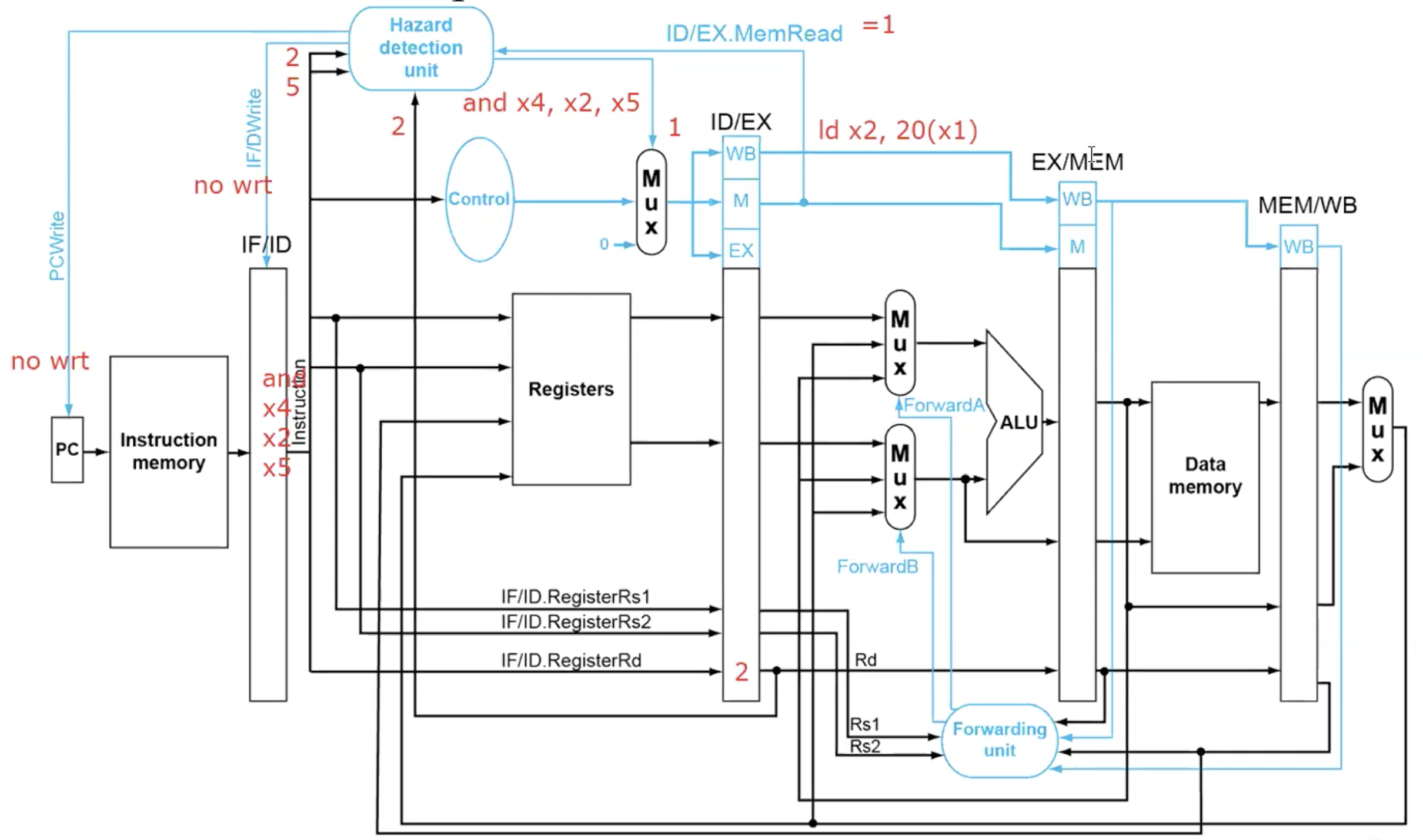
How to Stall the Pipeline
Force control values in ID/EX register to 0
EX,MEM and WB do nop(no-operation)
Prevent update of PC and IF/ID register
Using instruction is decoded again
Following instruction is fetched again
1-cycle stall allows MEM to read data for ld- Can subsequently forward to EX stage
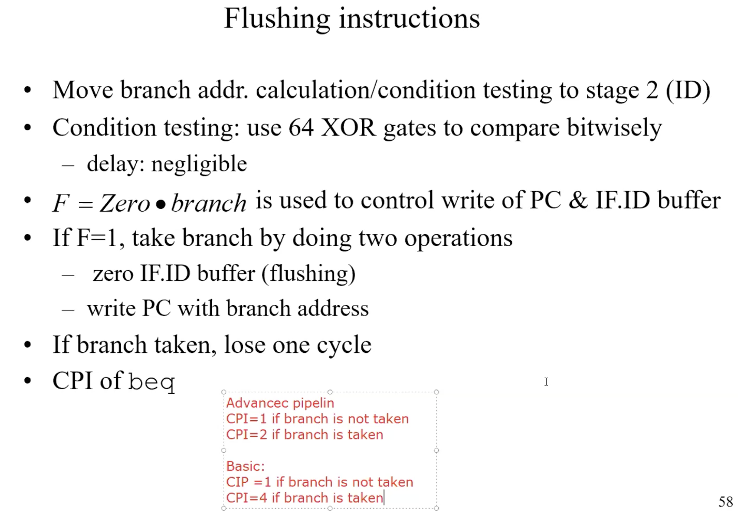
Branch Hazards
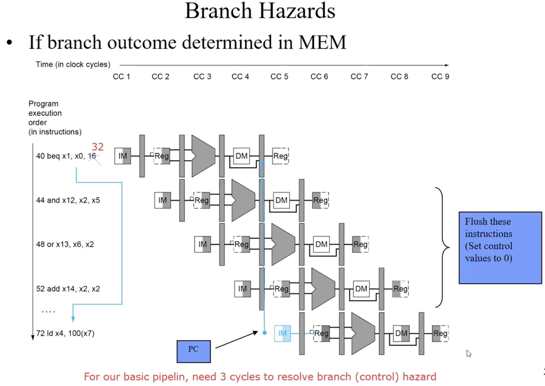
Handle Branch Hazards
just lose 1 cycle when branch is taken
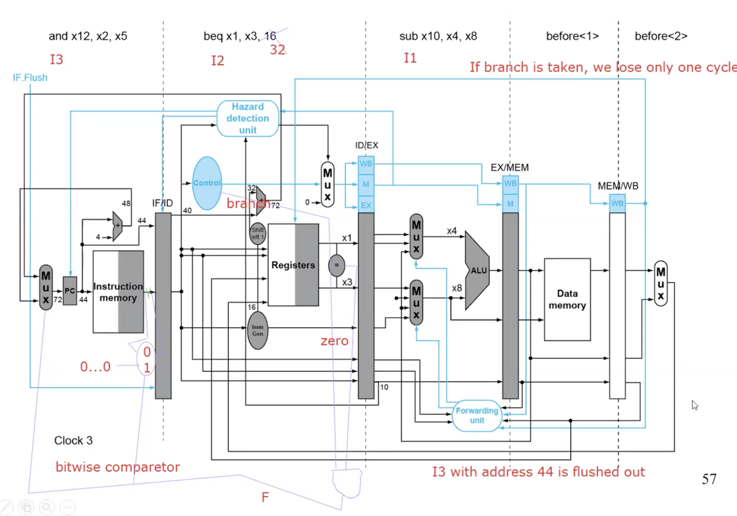
Flushing instrucion summary
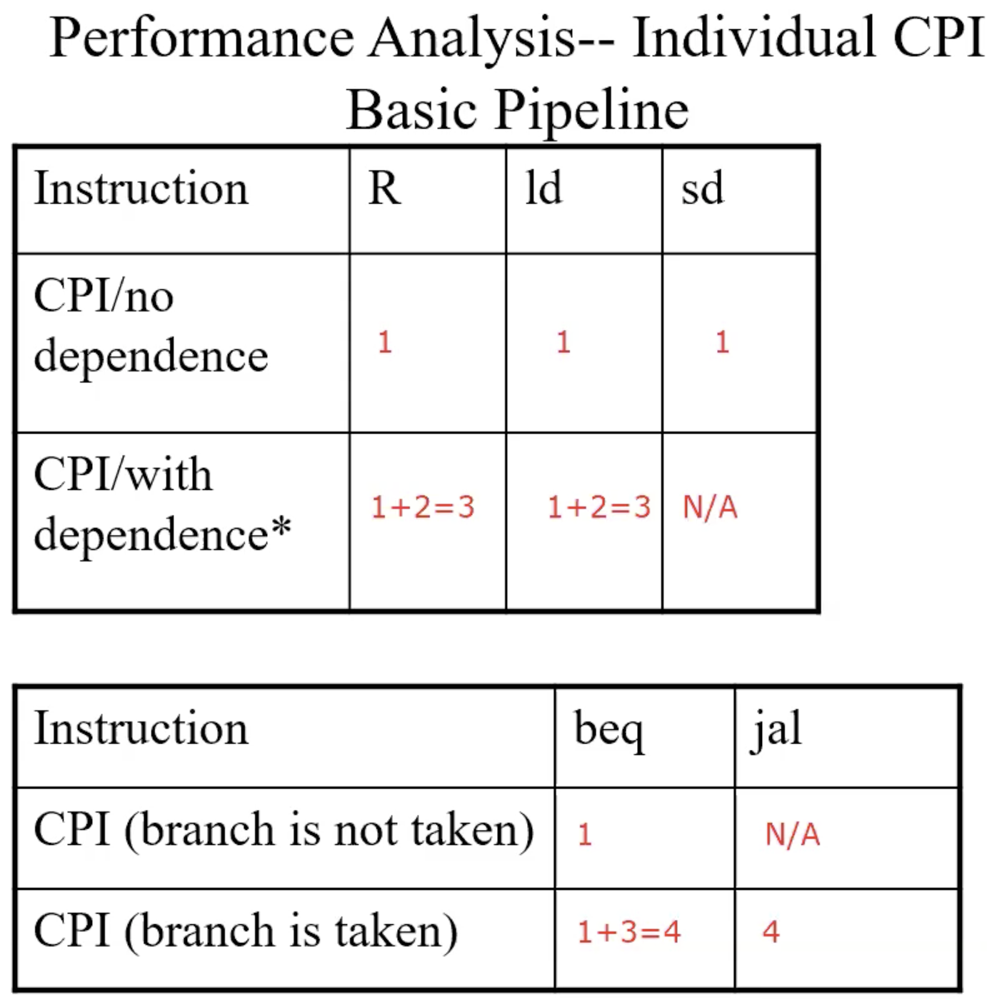
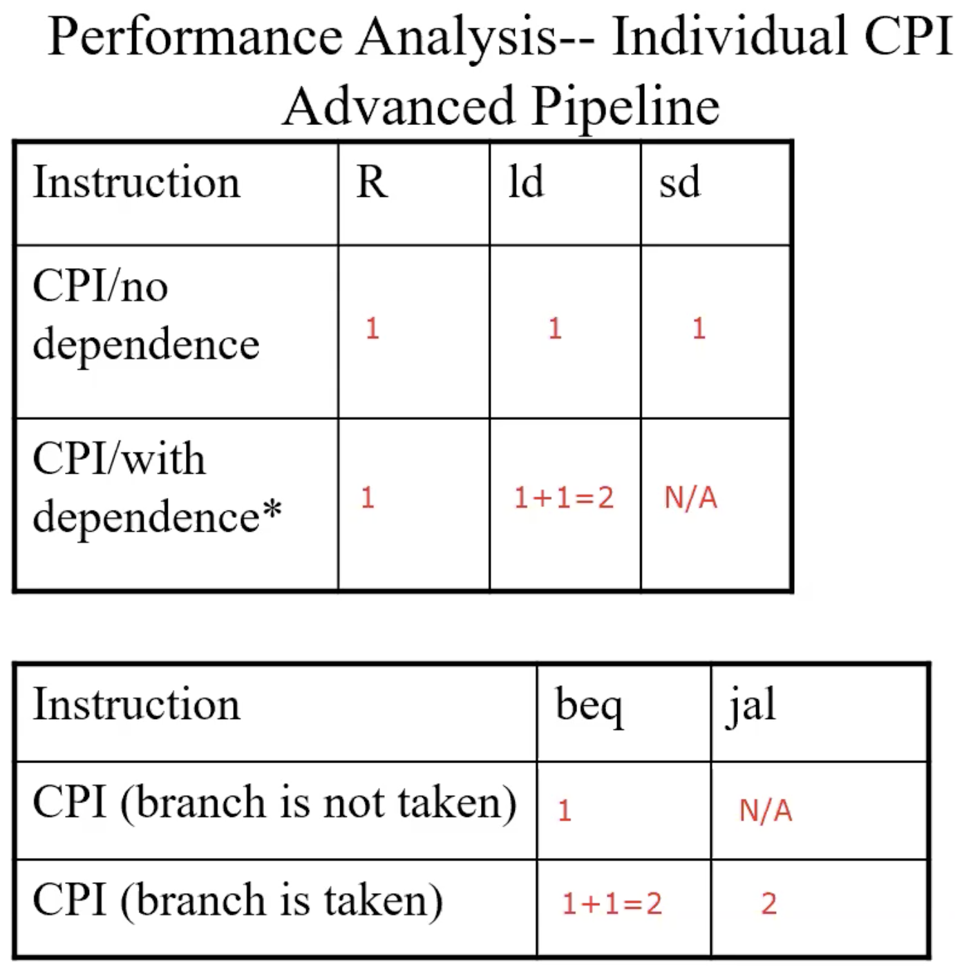
Performance Analysis – Individual CPI
Basic pipeline
Advanced pipeline
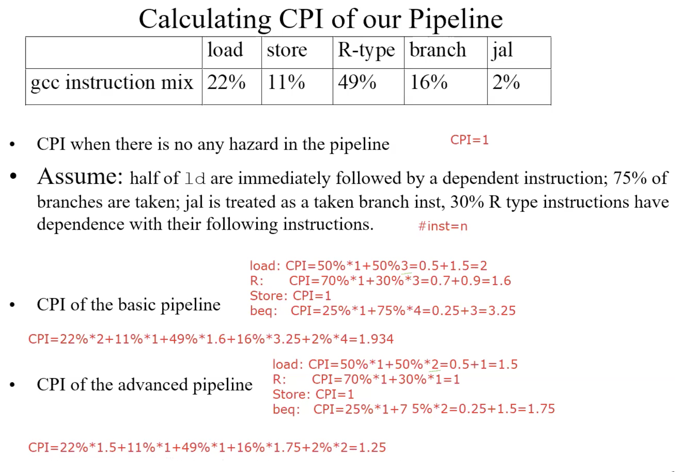
Example
Static Dual Issue
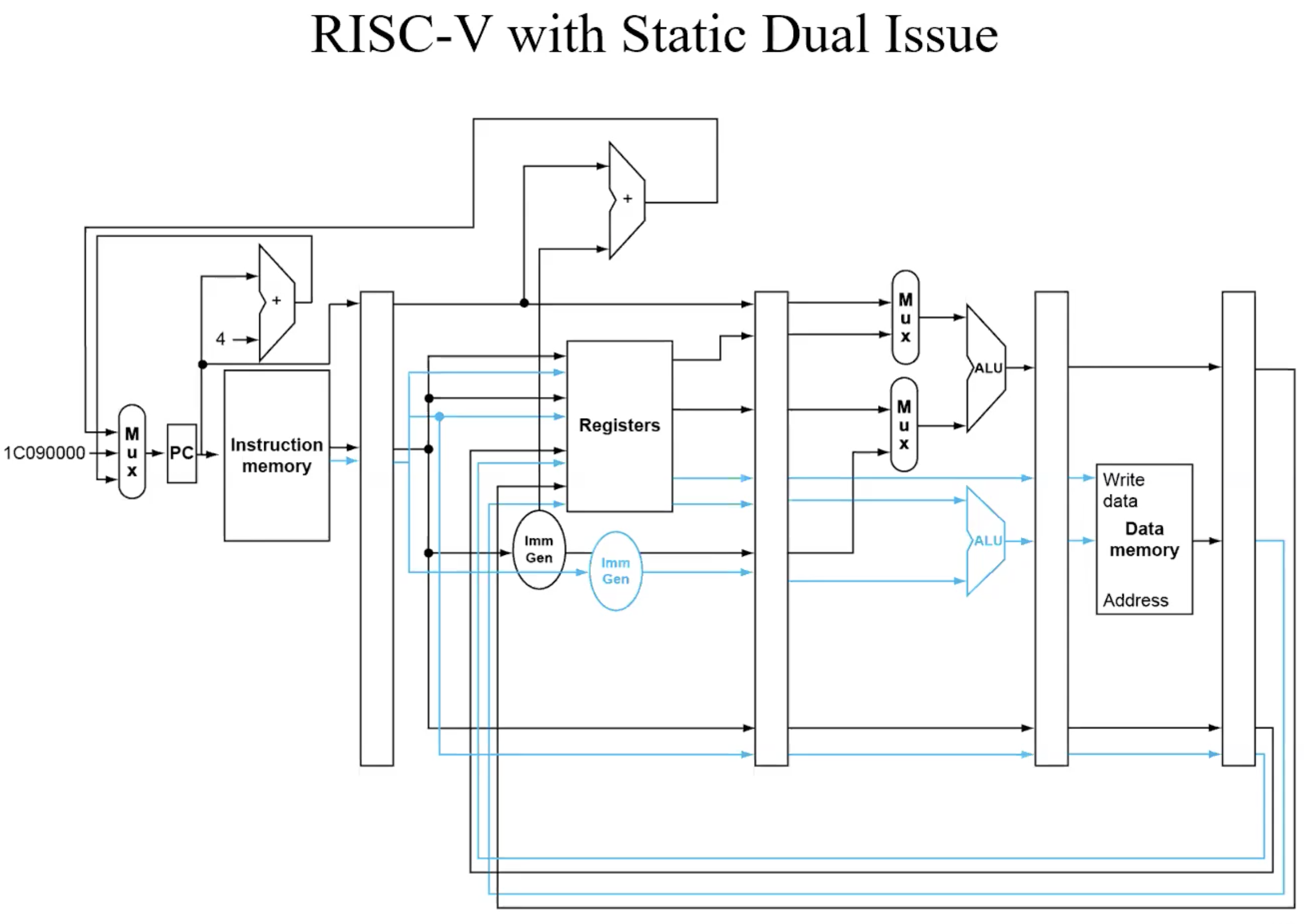
Example
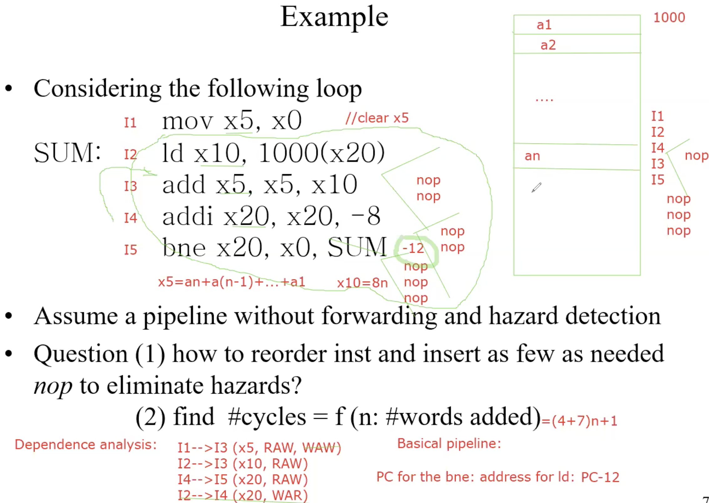
Powerful project
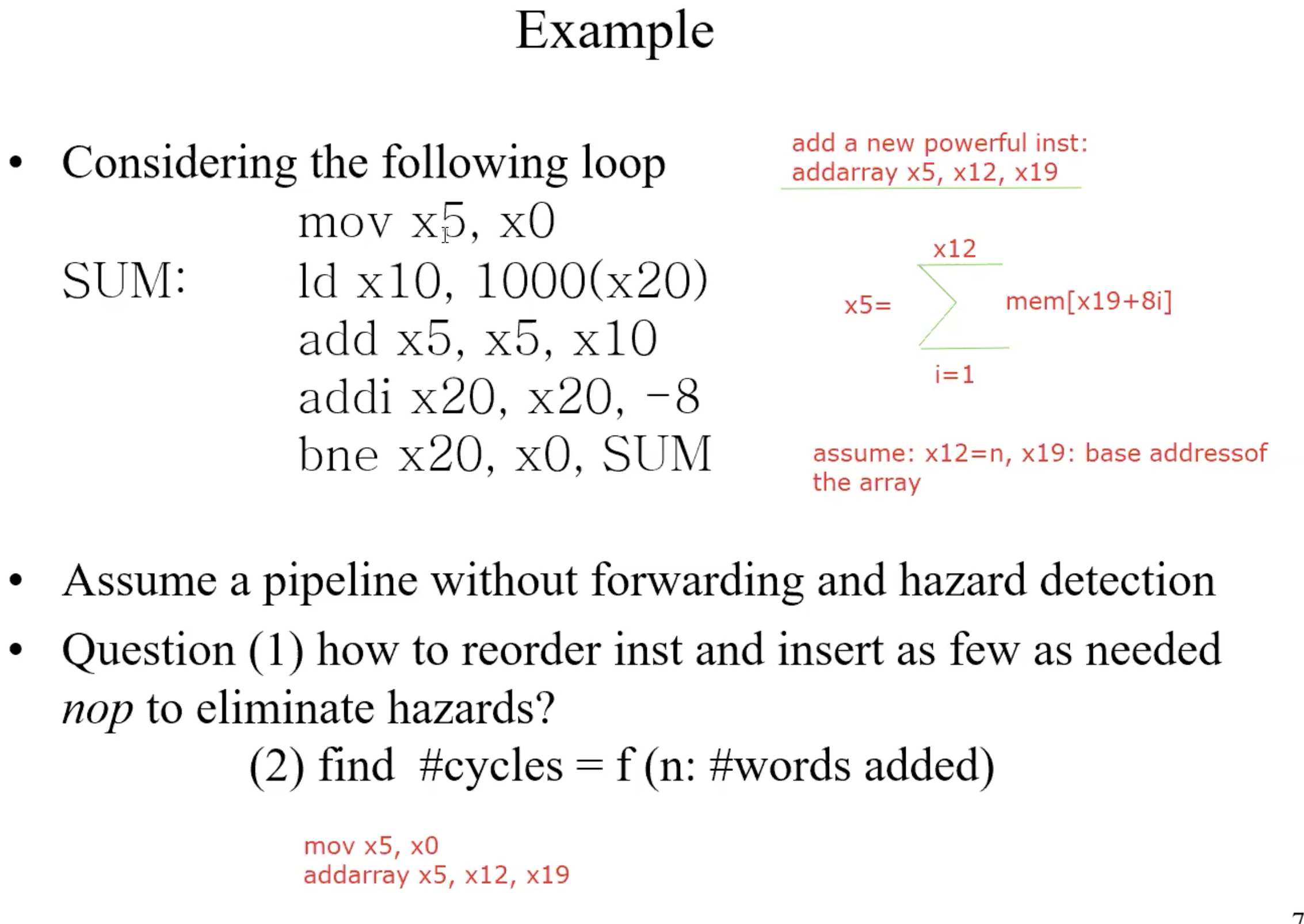
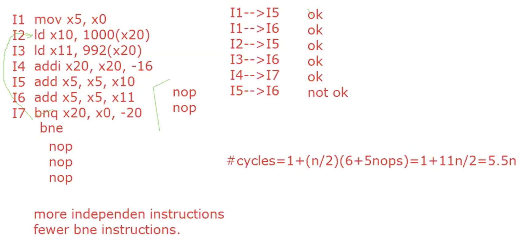
Loop unrolling
Replicate loop body to expose more parallelism
Reduces loop-control overhead
Example enroll by 2,and 3
Concluding remarks
ISA influences design of datapath and control
Pipelining improves instruction throughput using parallelism
More instructions completed persecond
Latency for each instruction not reducedHazards: structural, data, control
Chapter 5
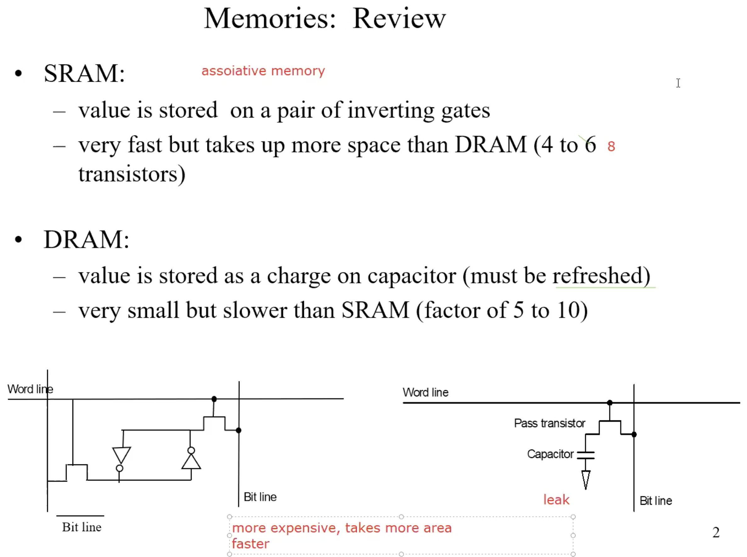
Memory hierarchy
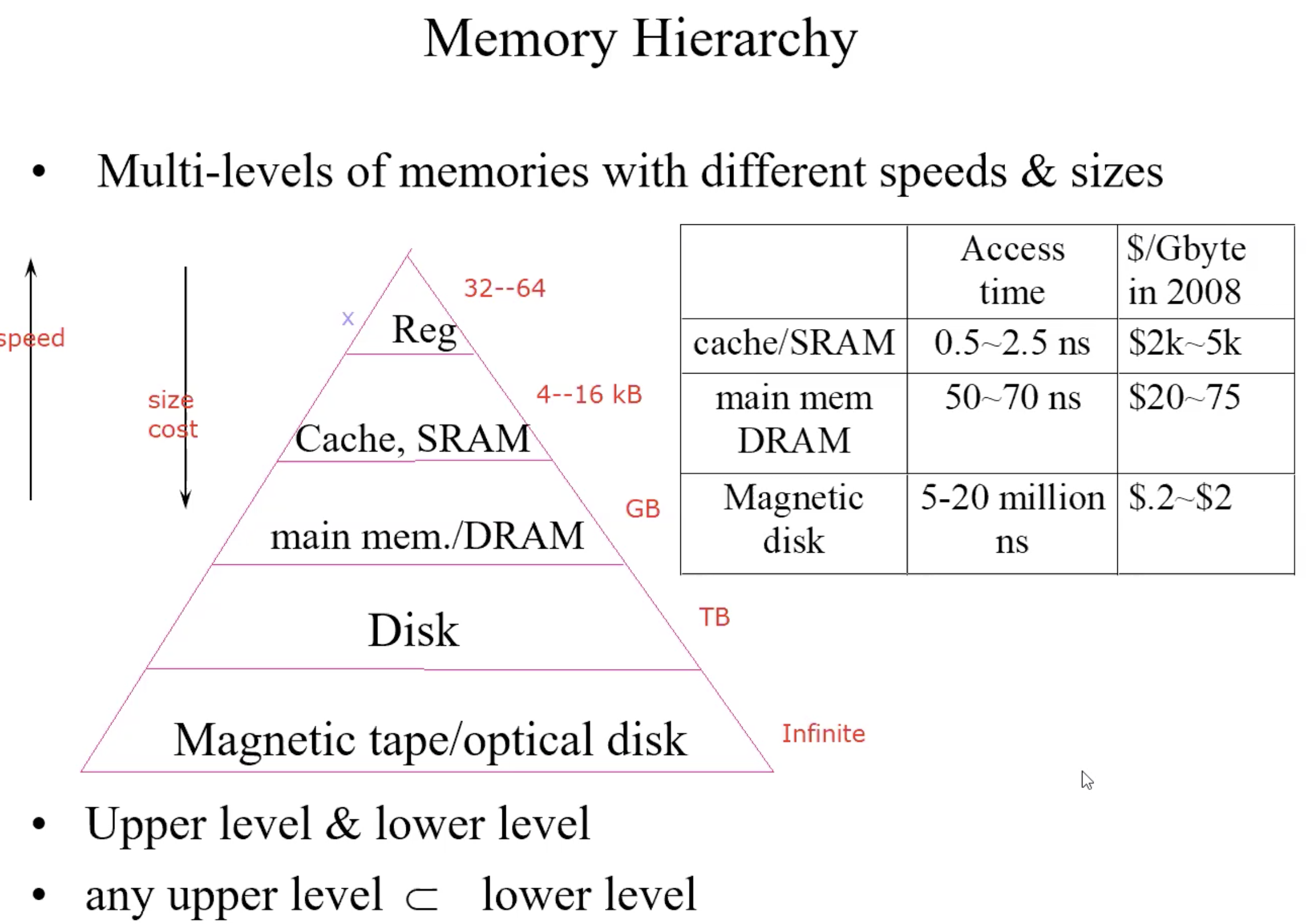
Goal of Memory hierarchy
- speed of highest level (cache)
- size of lowest level (disk)
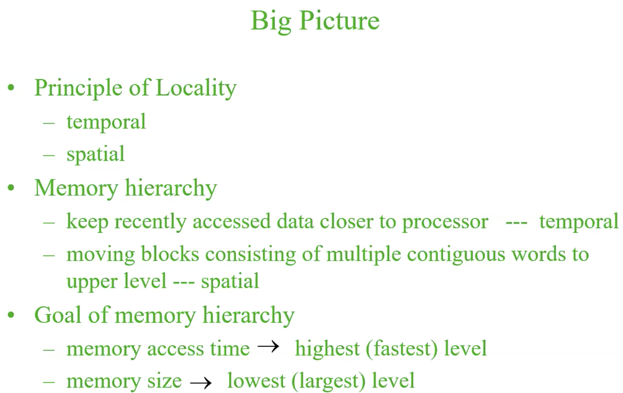
Principle of locality
Program access a relative small portion of their address space — if an item is referenced.
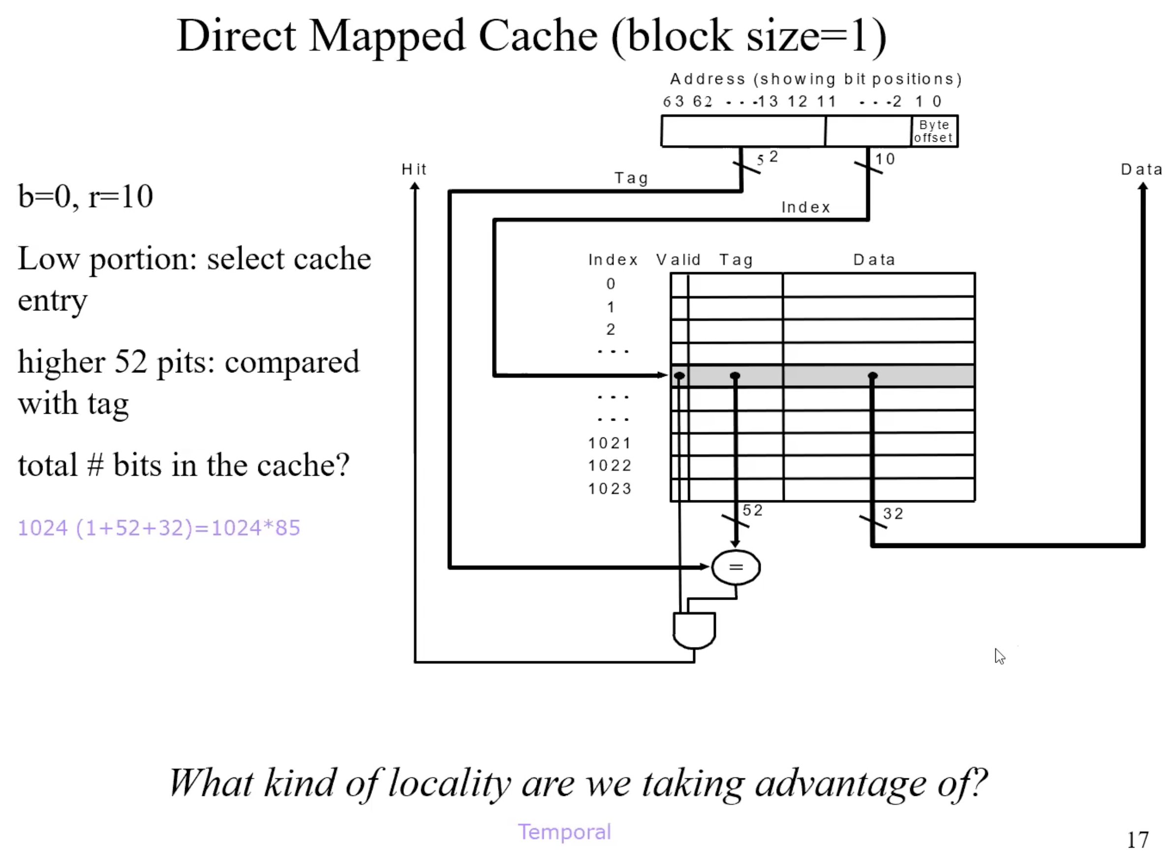
- it will tend to be referenced again soon – temporal locality
- nearby items will tend to be referenced soon – spatial locality
Big picture
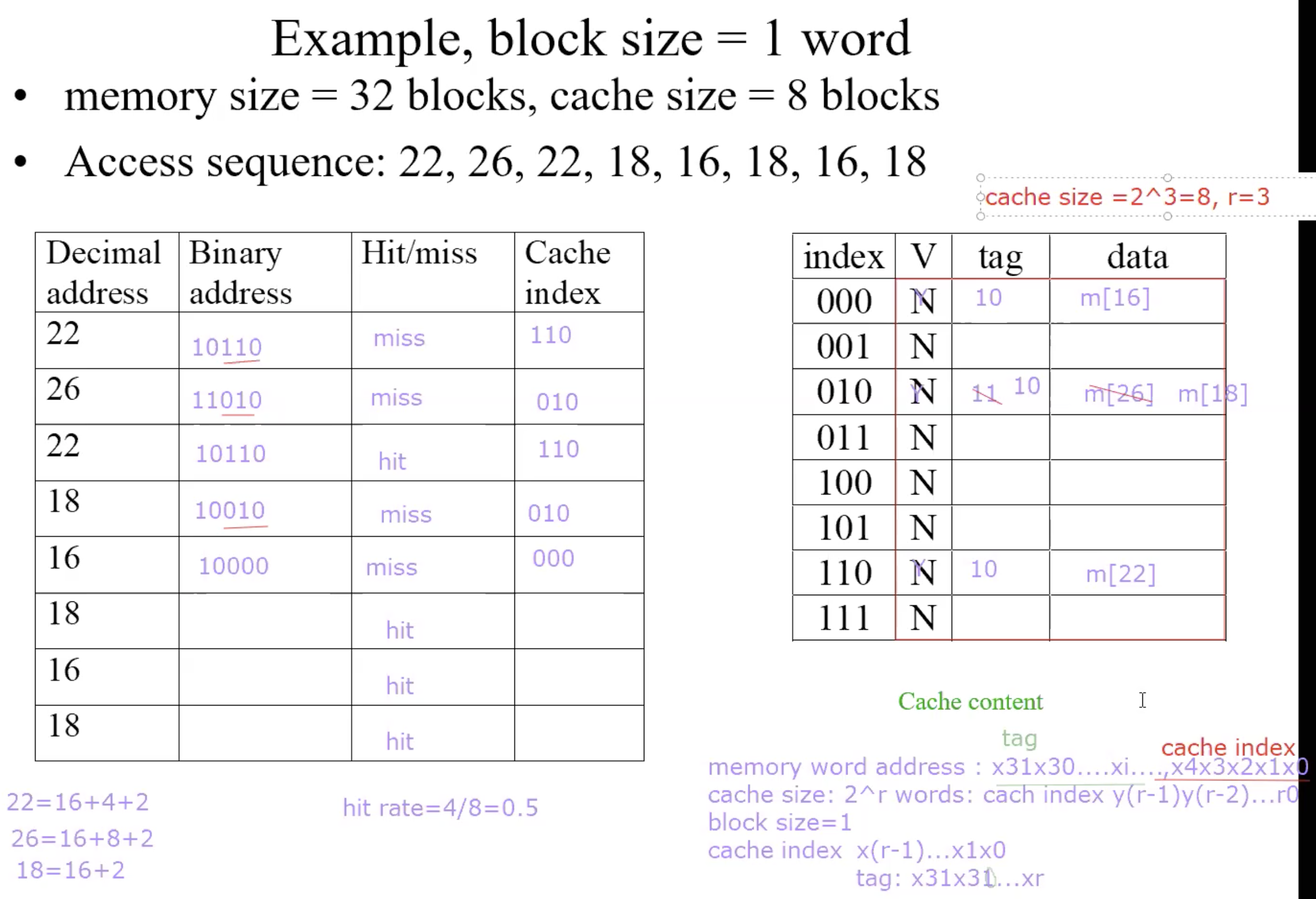
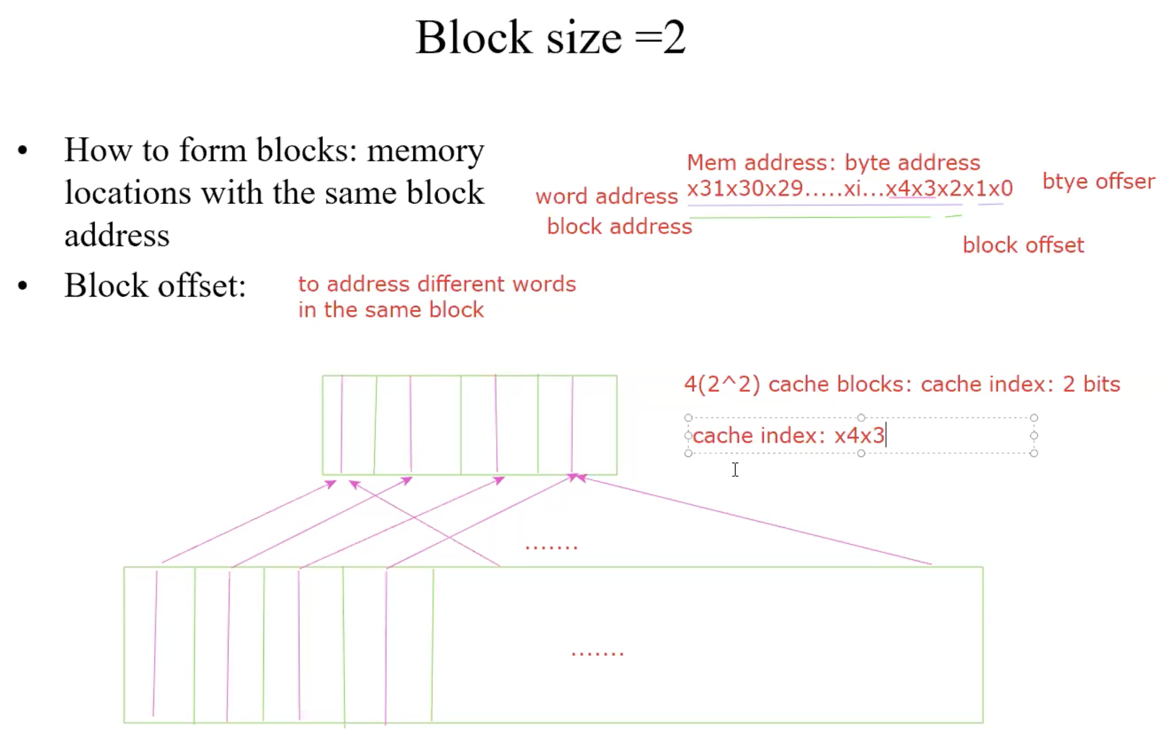
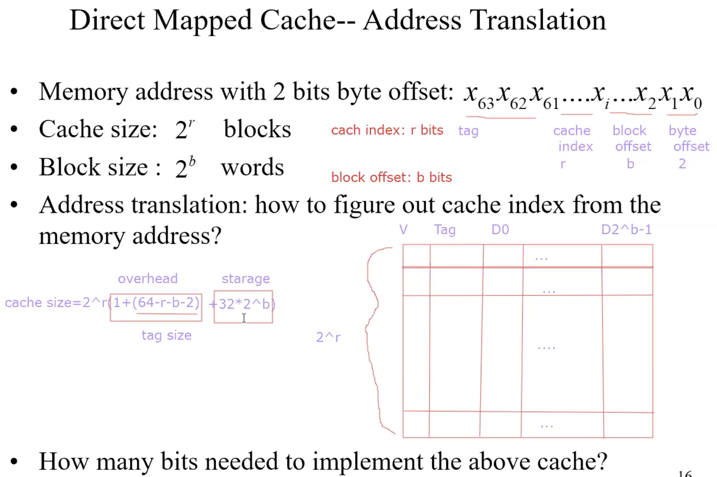
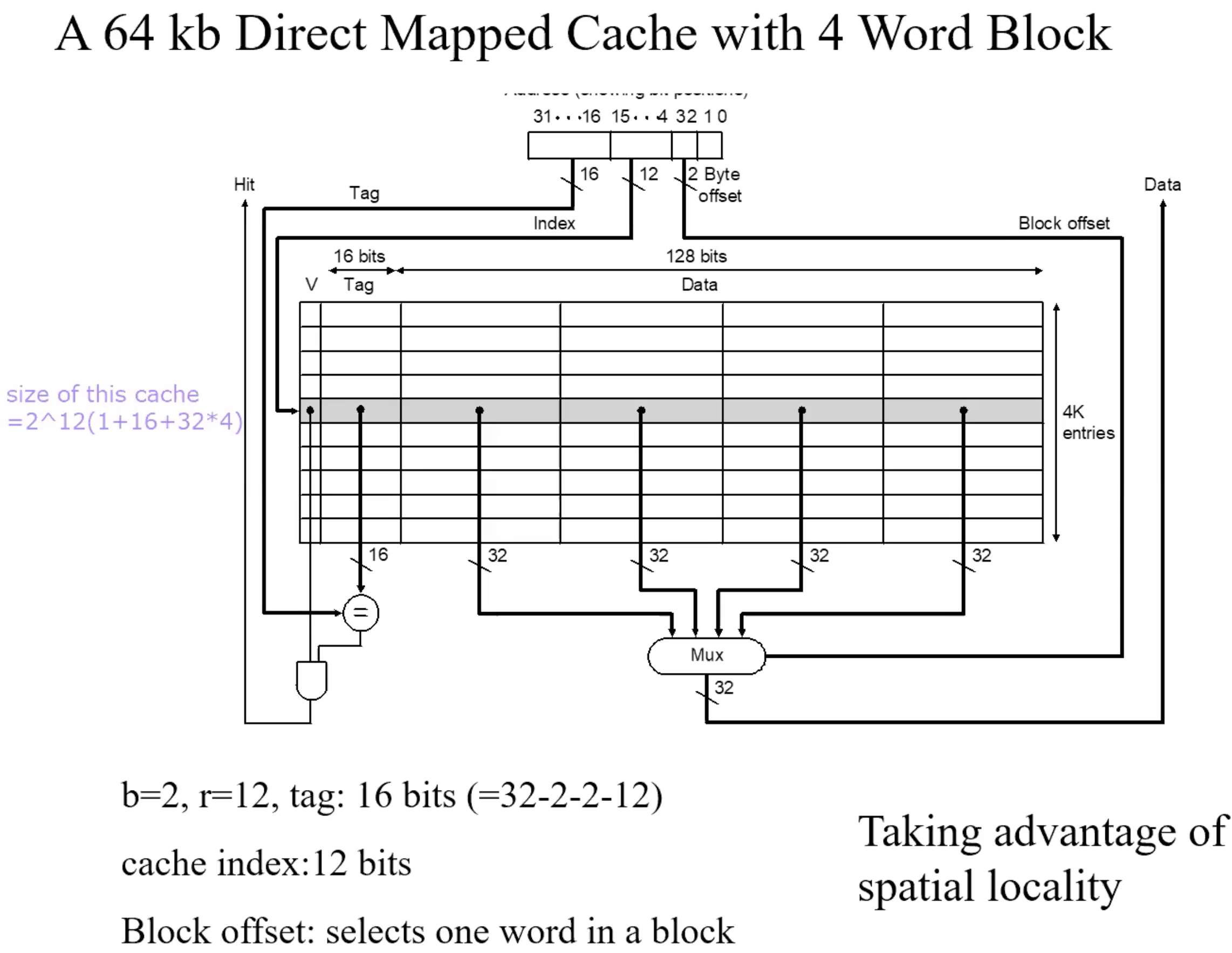
Address mapping
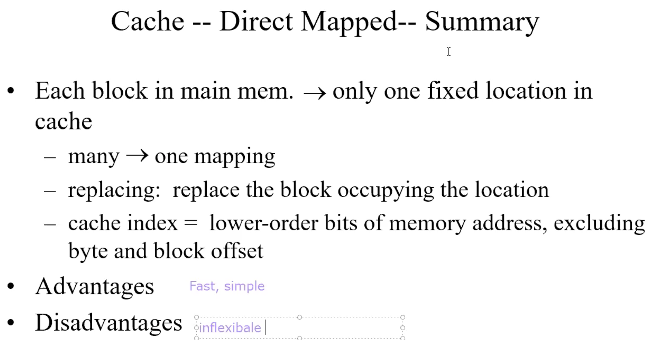
Direct address mapping
Lower-order 3 bits of M.address = C.index
Memory locations with the same lower-order 3 bits share the same cache
location-due to spatial localityThe block in cache to be replaced is fixed
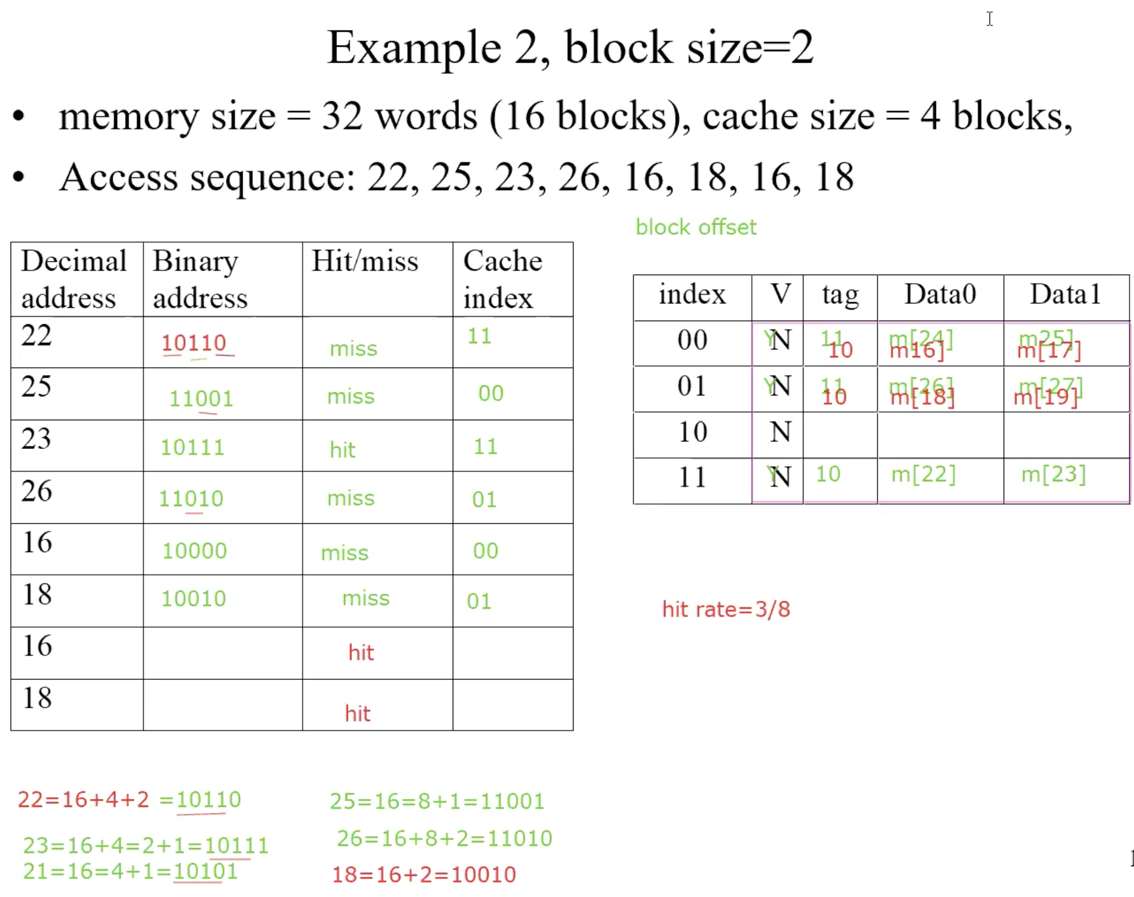
How do I know if the data is what I want?
Tags: consist of higher-order bits of memory addresses
Example
Blocksize = 2
Example
Summary
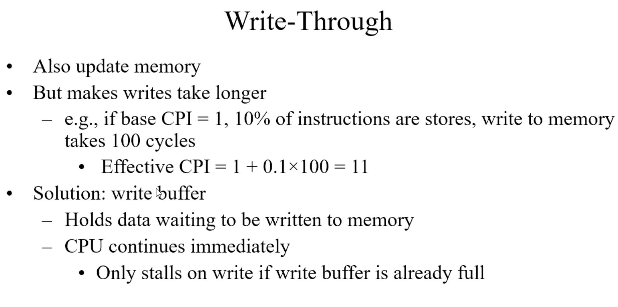
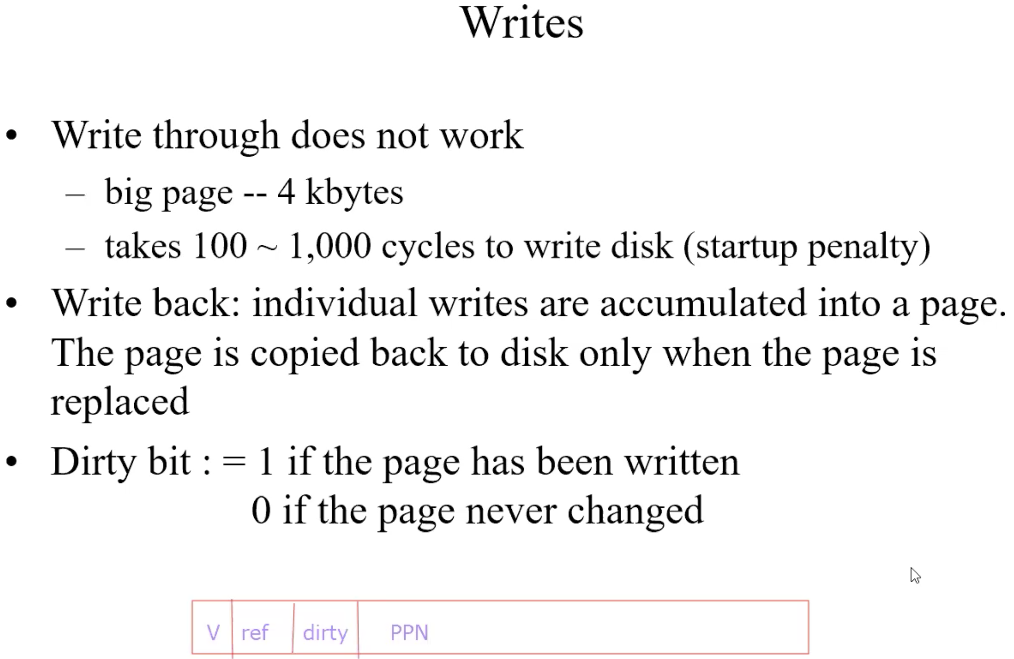
Write through
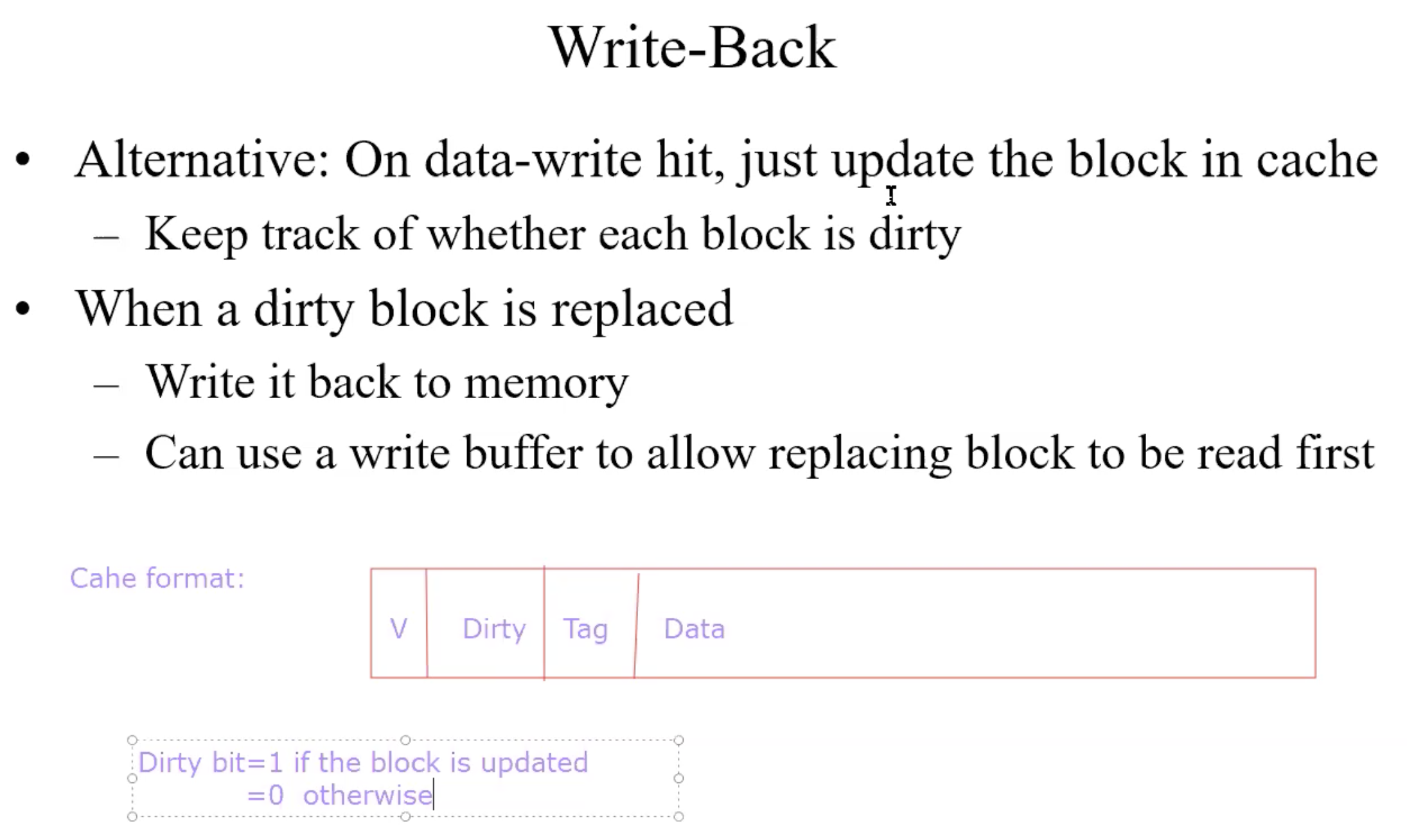
Write back
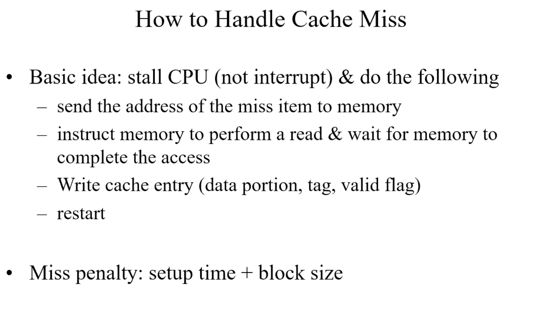
Handle cache miss
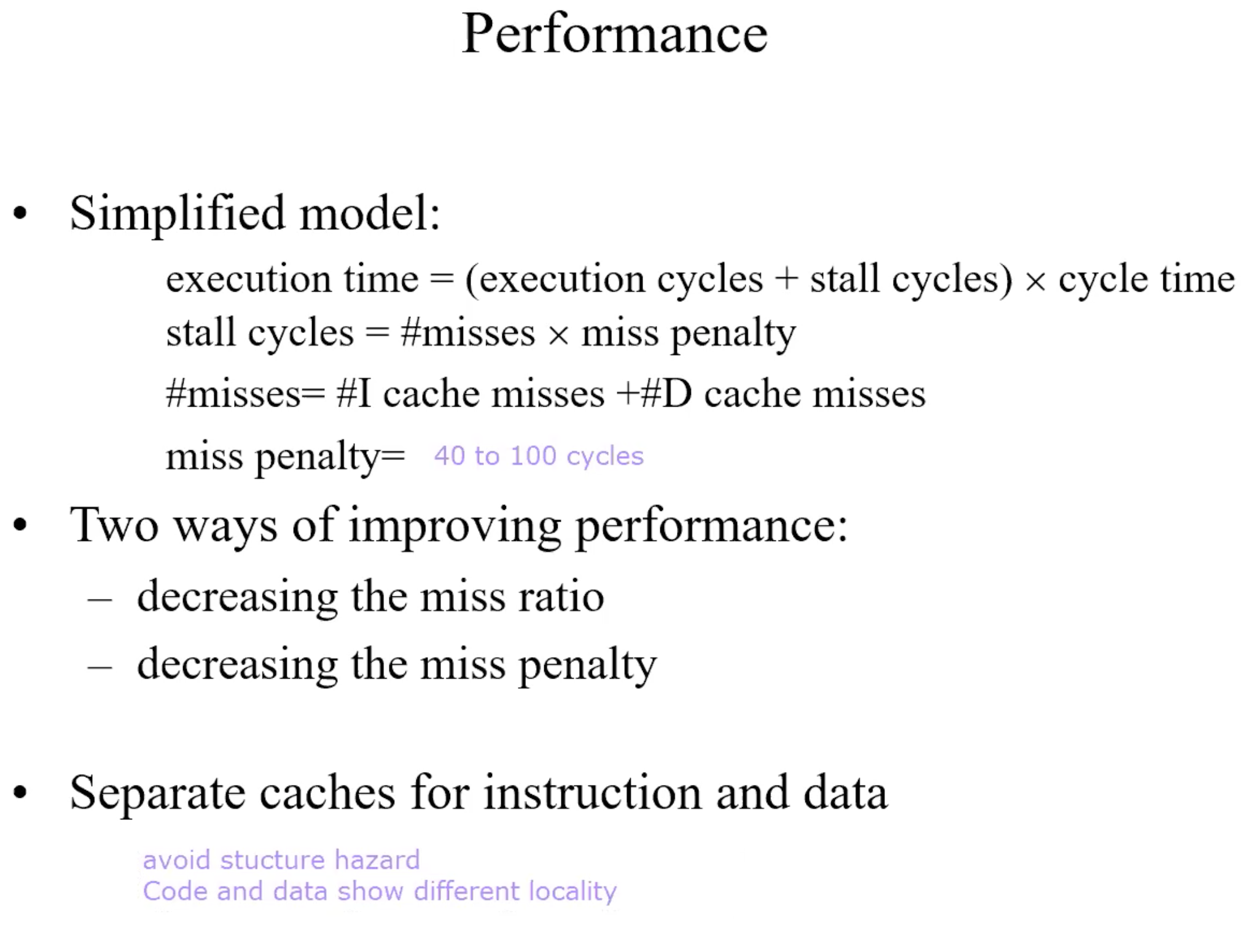
Performance
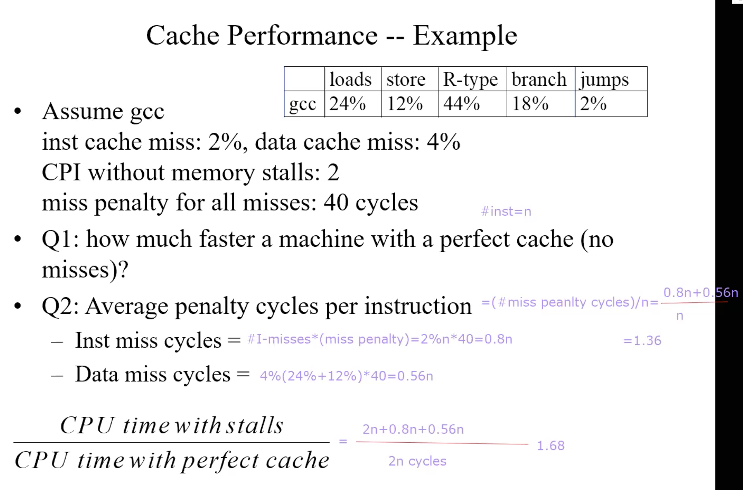
Performance Example
Cache Misses: 3 C’s
- Complusory miss(cold start misses): A cache miss caused by the 1st access to a block that has never been in the cache.
- Capacity miss: A cache miss that occurs because of the cache size.
- Conflict miss(collision miss): A cache miss that occurs when multiple blocks compete for the same set while other sets are available.
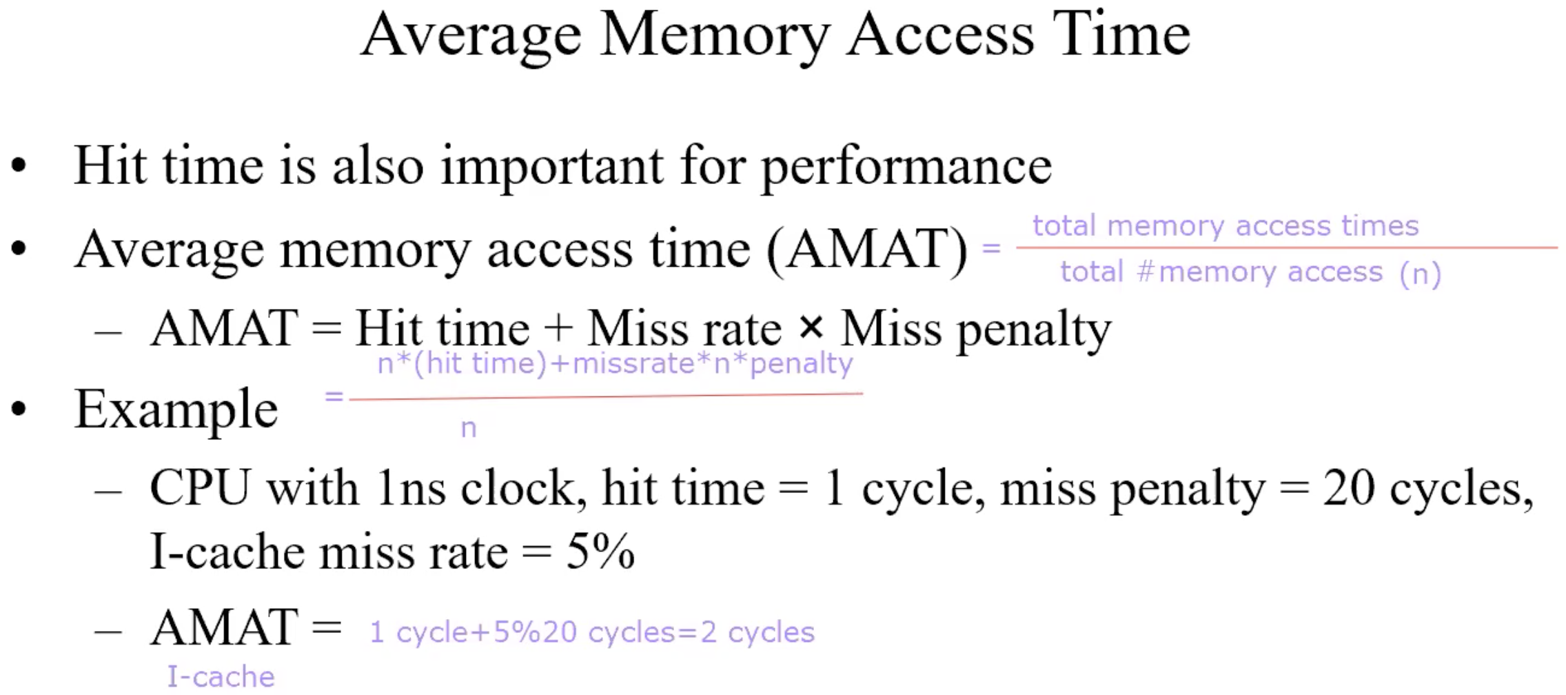
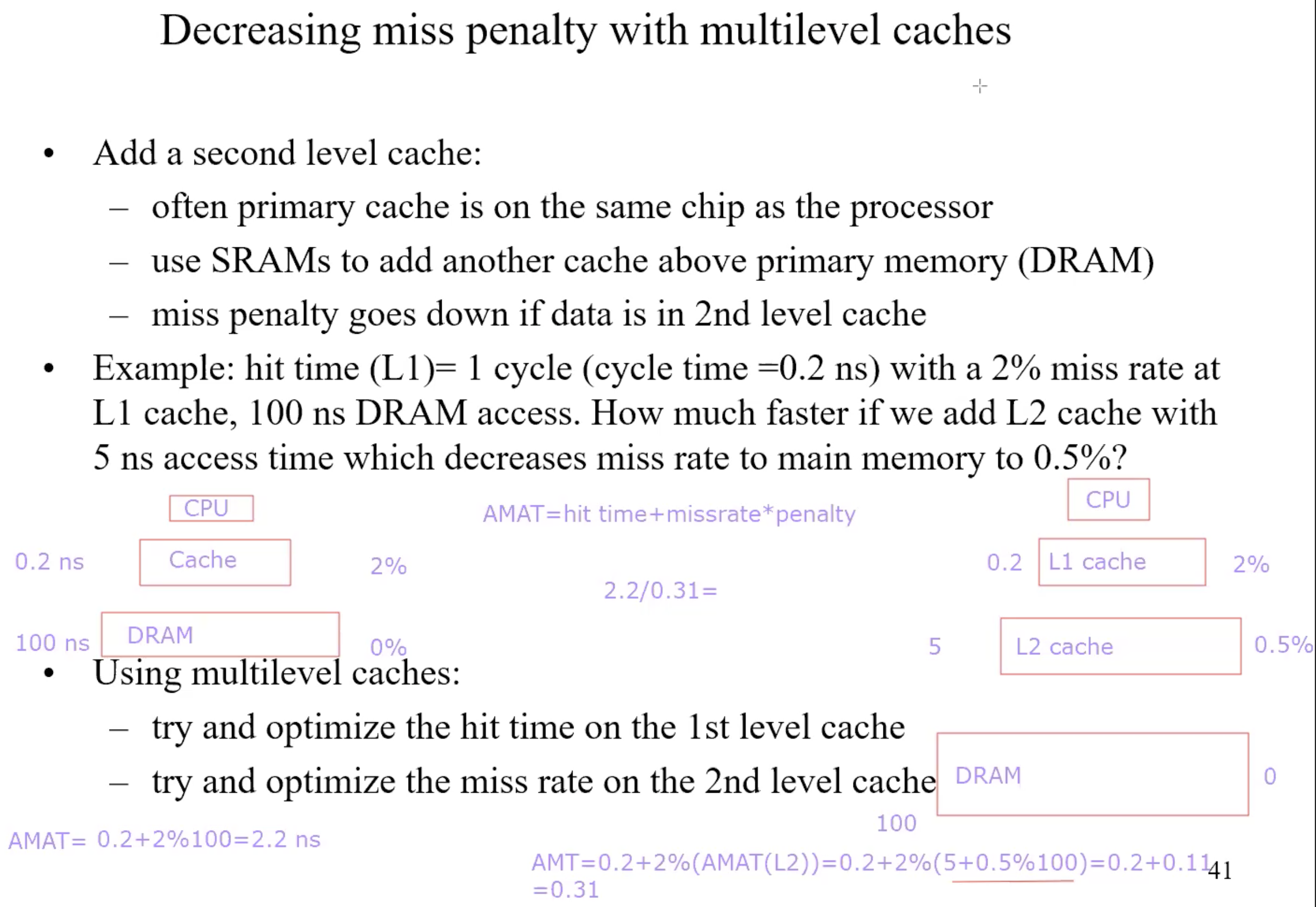
Average Memory Access Time
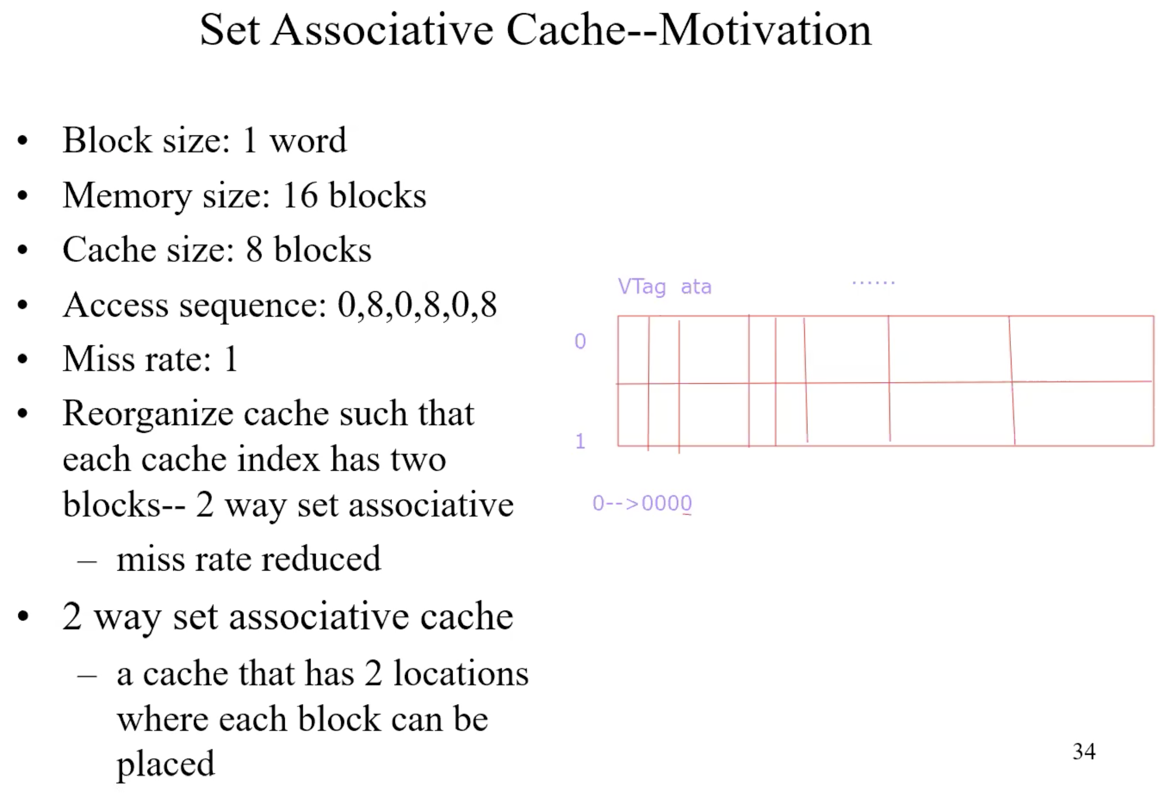
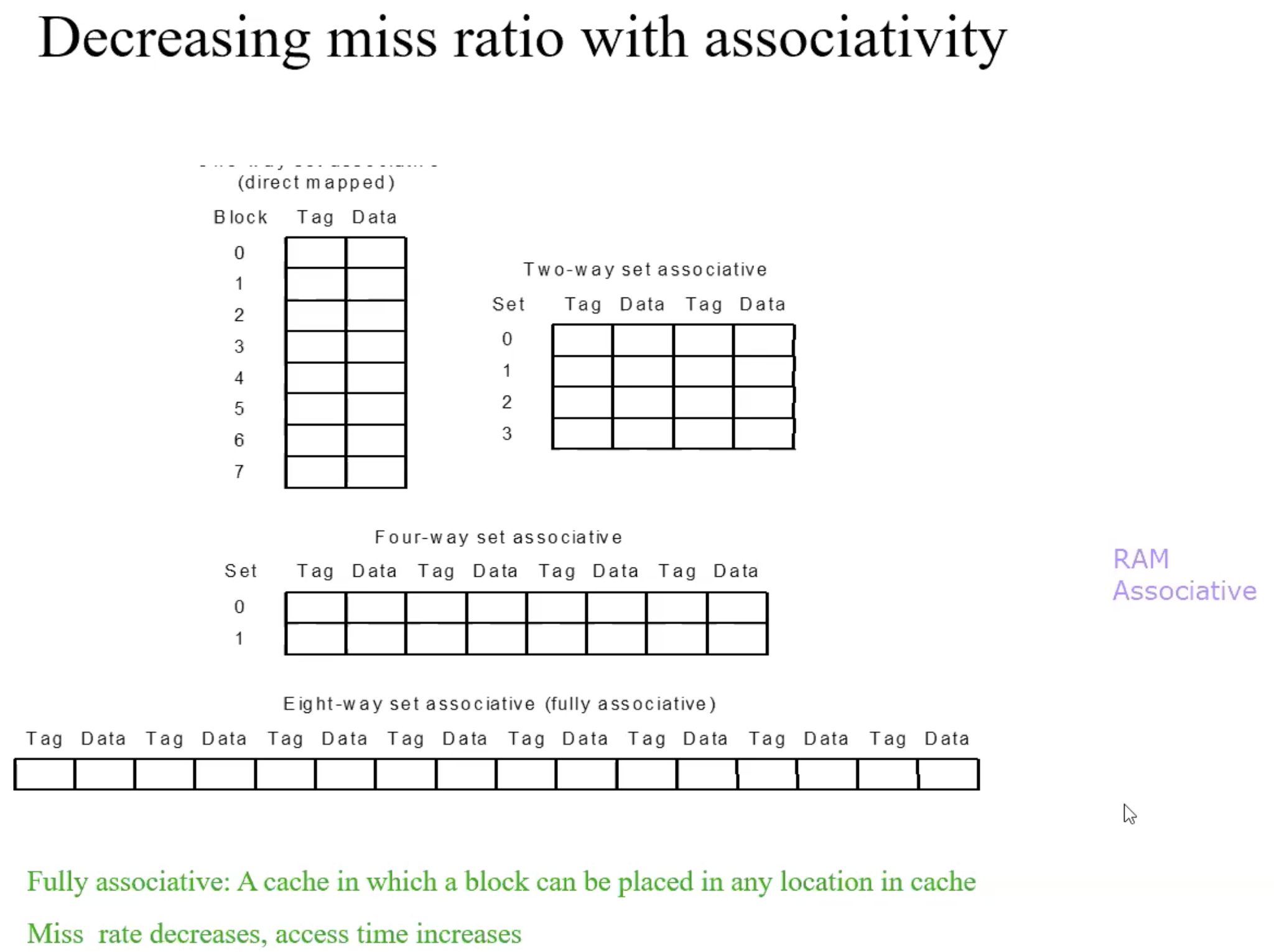
Set Associative Cache–Motivation
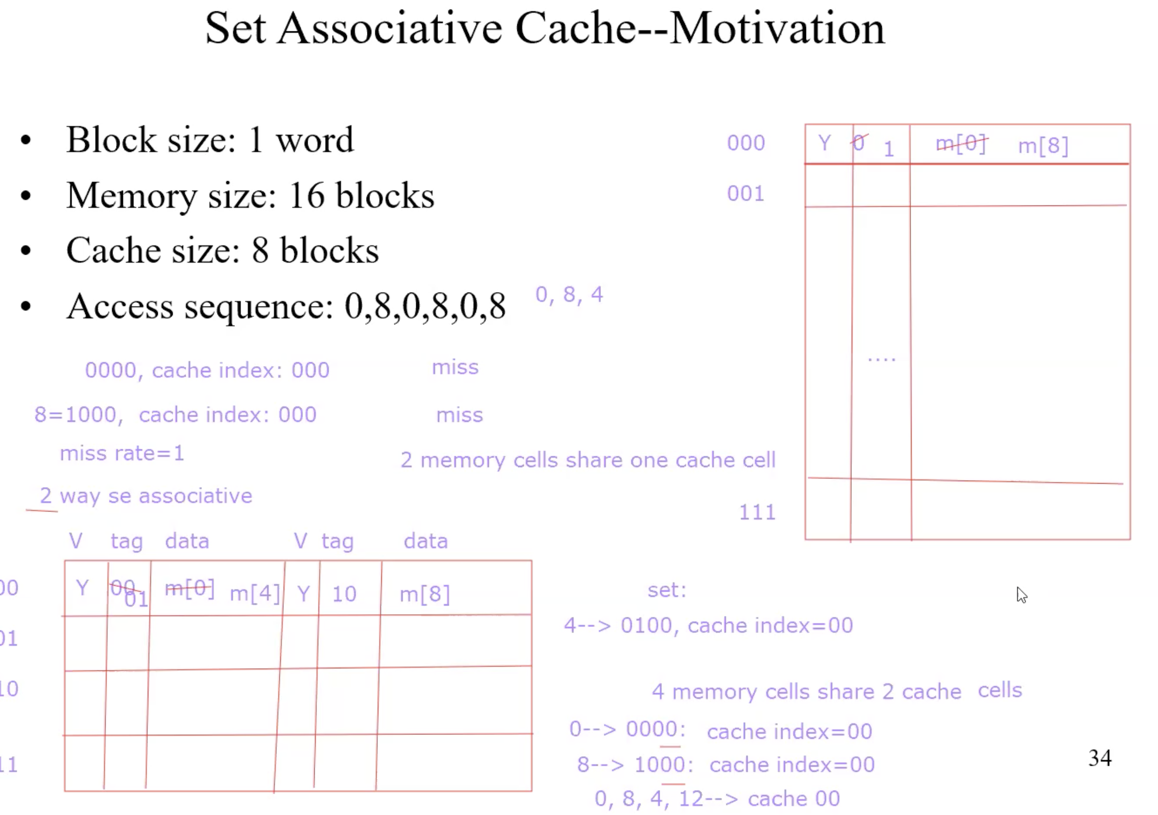
Fully associative
Allow a given block to go in any cache entry
Requires all entries to be searched at once
Comparator per entry(expensive)n-way set associative
Each set contains n entries
Block number determines which set: (Block number) modulo(#Sets in cache)
Search all entries in a given set at once
n comparators(less expensive)
Comparison of 2 caches with 8 words
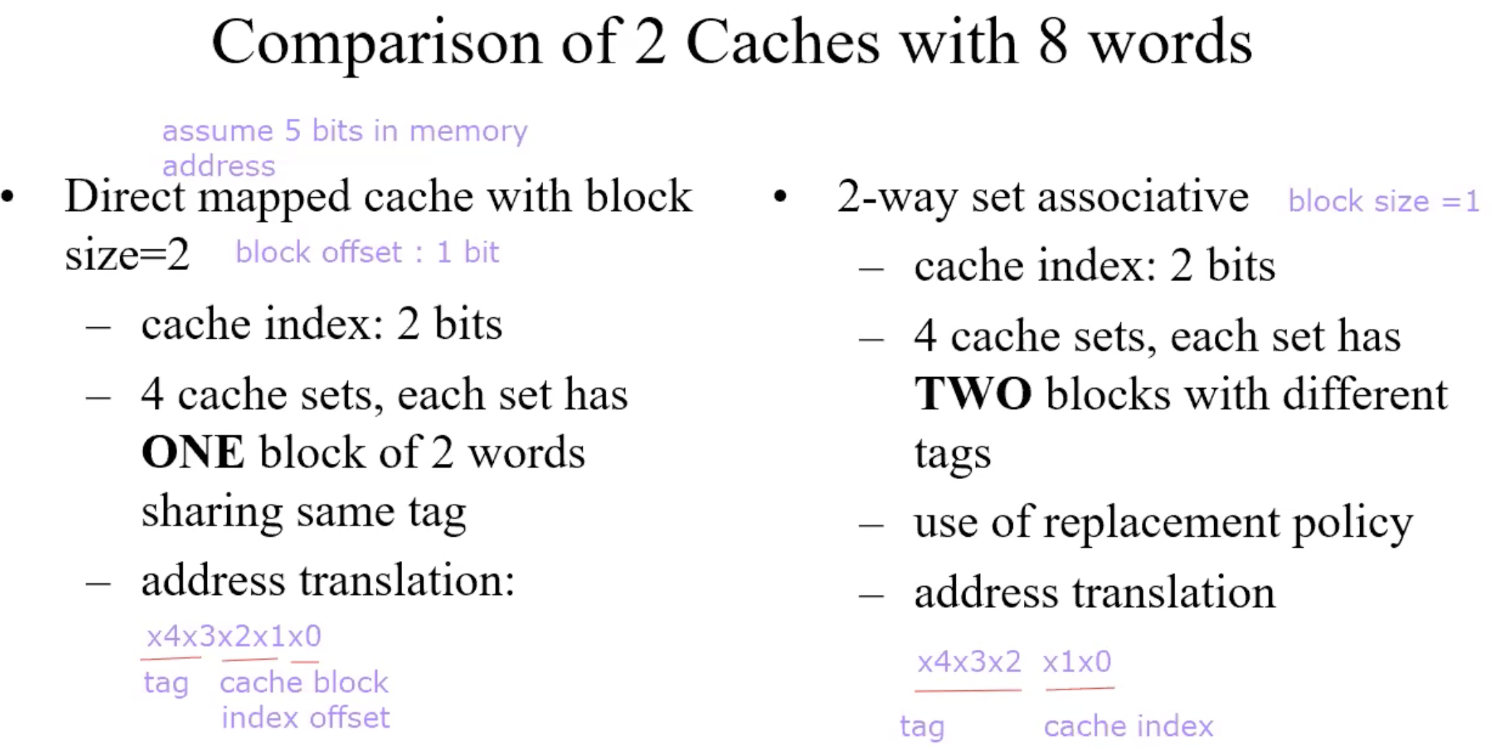
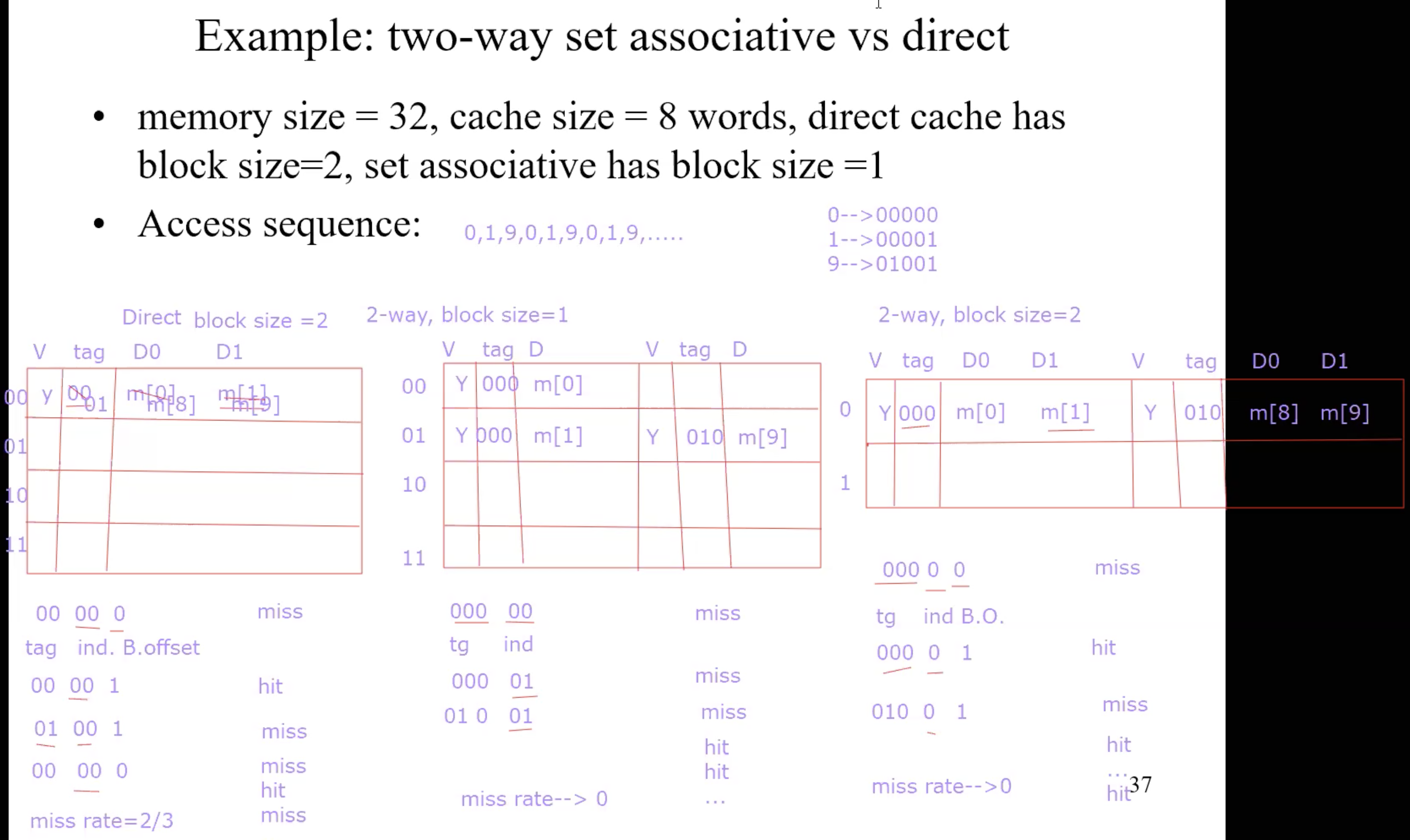
Miss ratio with associativity
Increase associativity, decrease miss ratio, increase the return time(because it need to search all tag)
Multi-cache-level
Virtual Memory
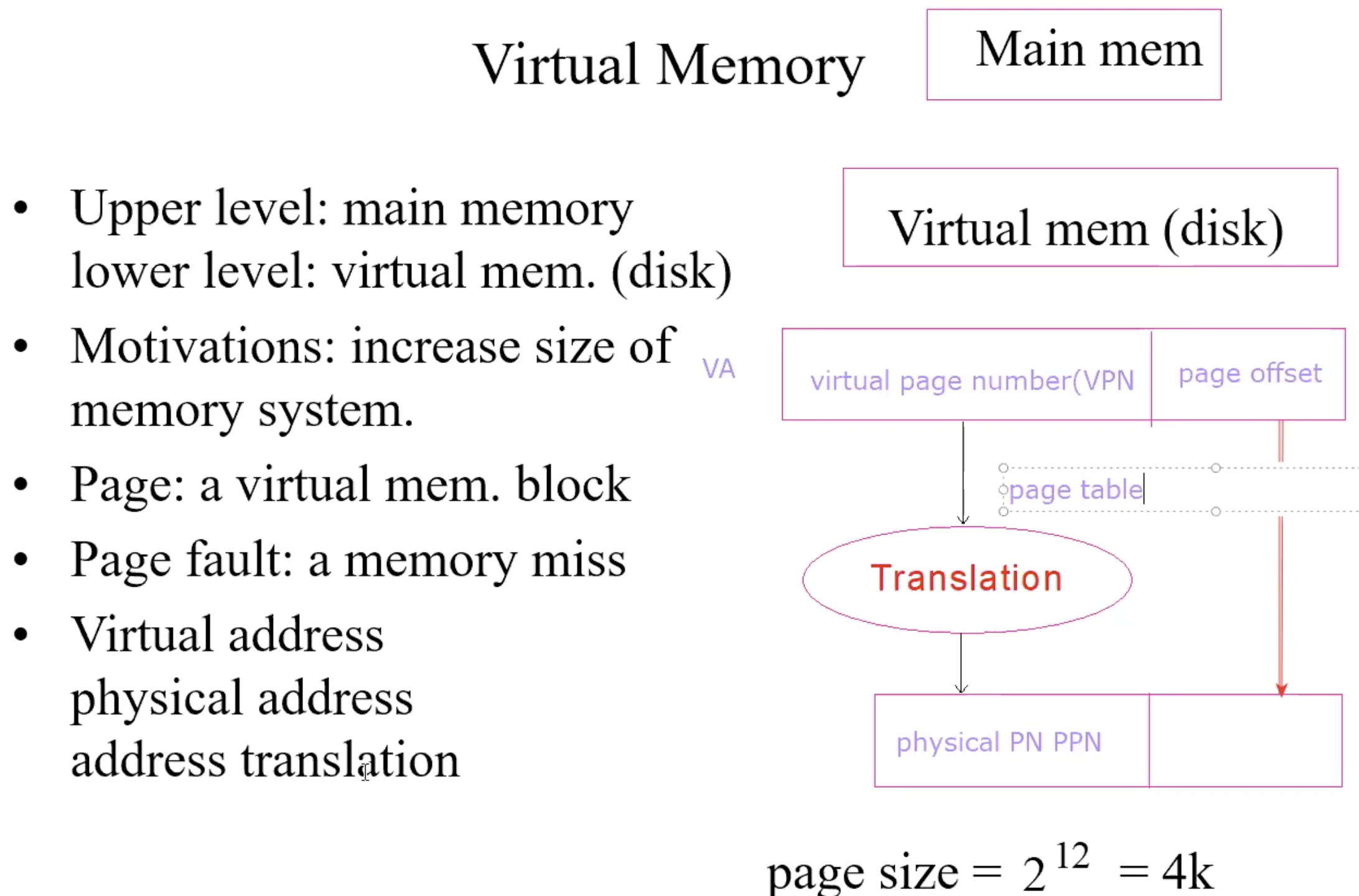
Addressing Mapping & Address Translation
Address mapping–fully associative:
a page can go any page frame in physical memory
Address translation
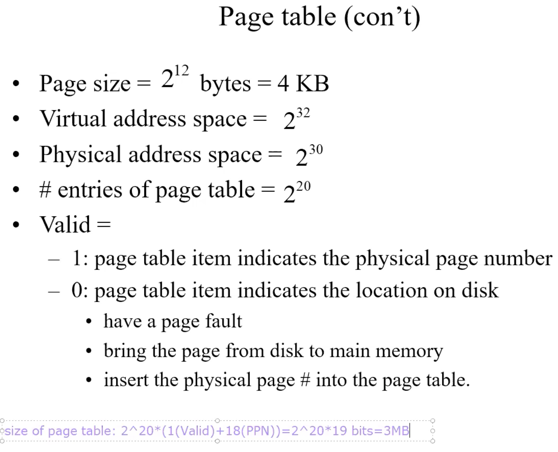
by page table: tells if a page is in physical memory; if it is in, provides the physical address
each program has a page table
page table stored in main memoryPage table register: pointing to the page table
Page Table
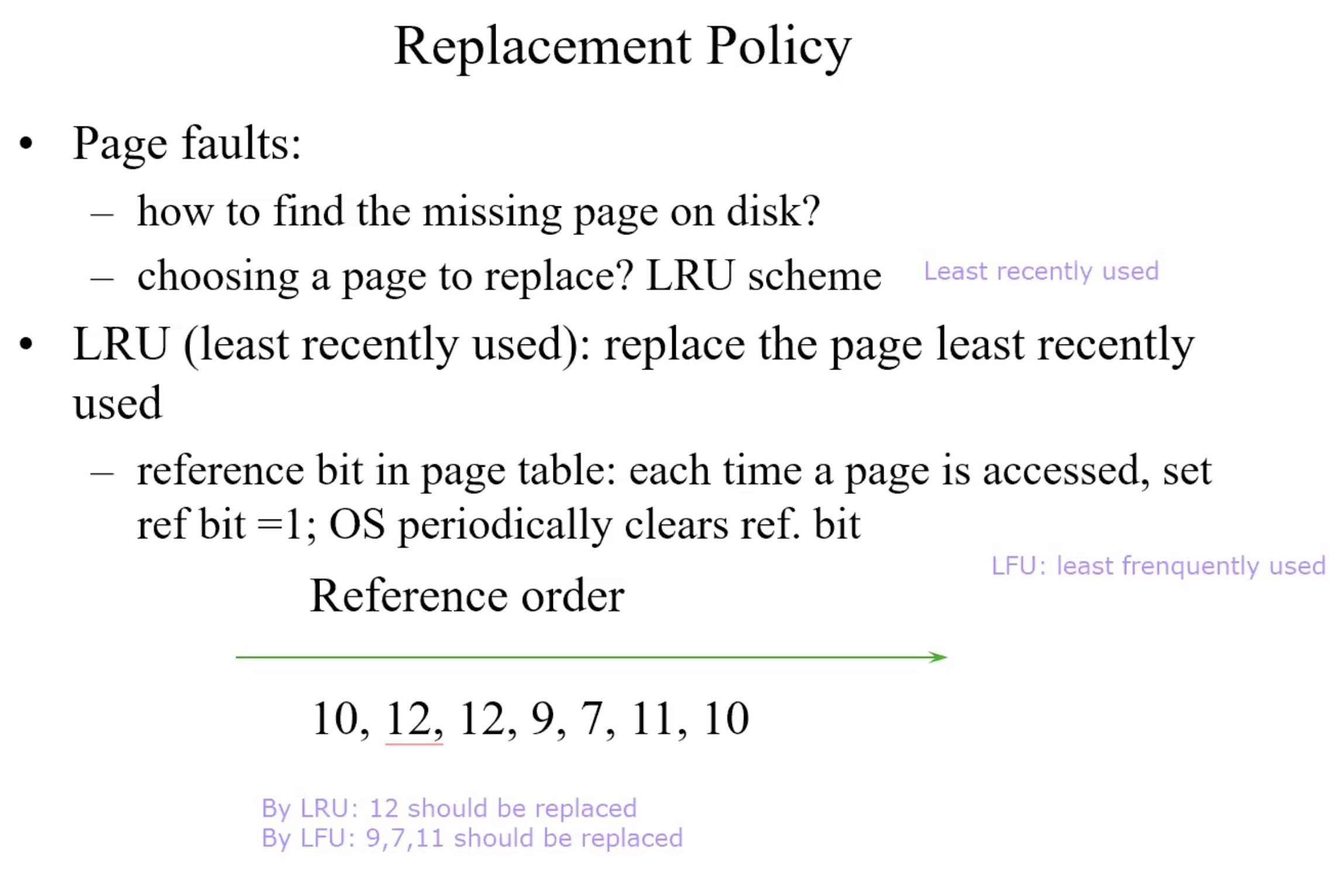
Replacement Policy
Write
TLB–cache of page table
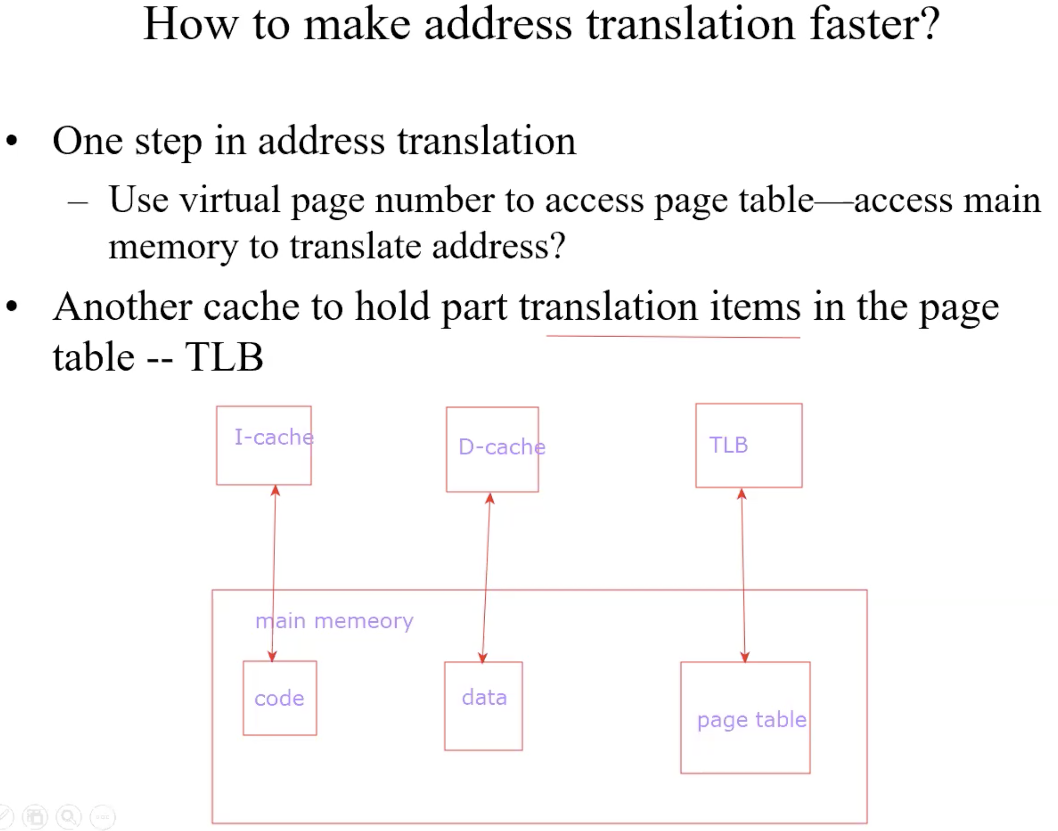
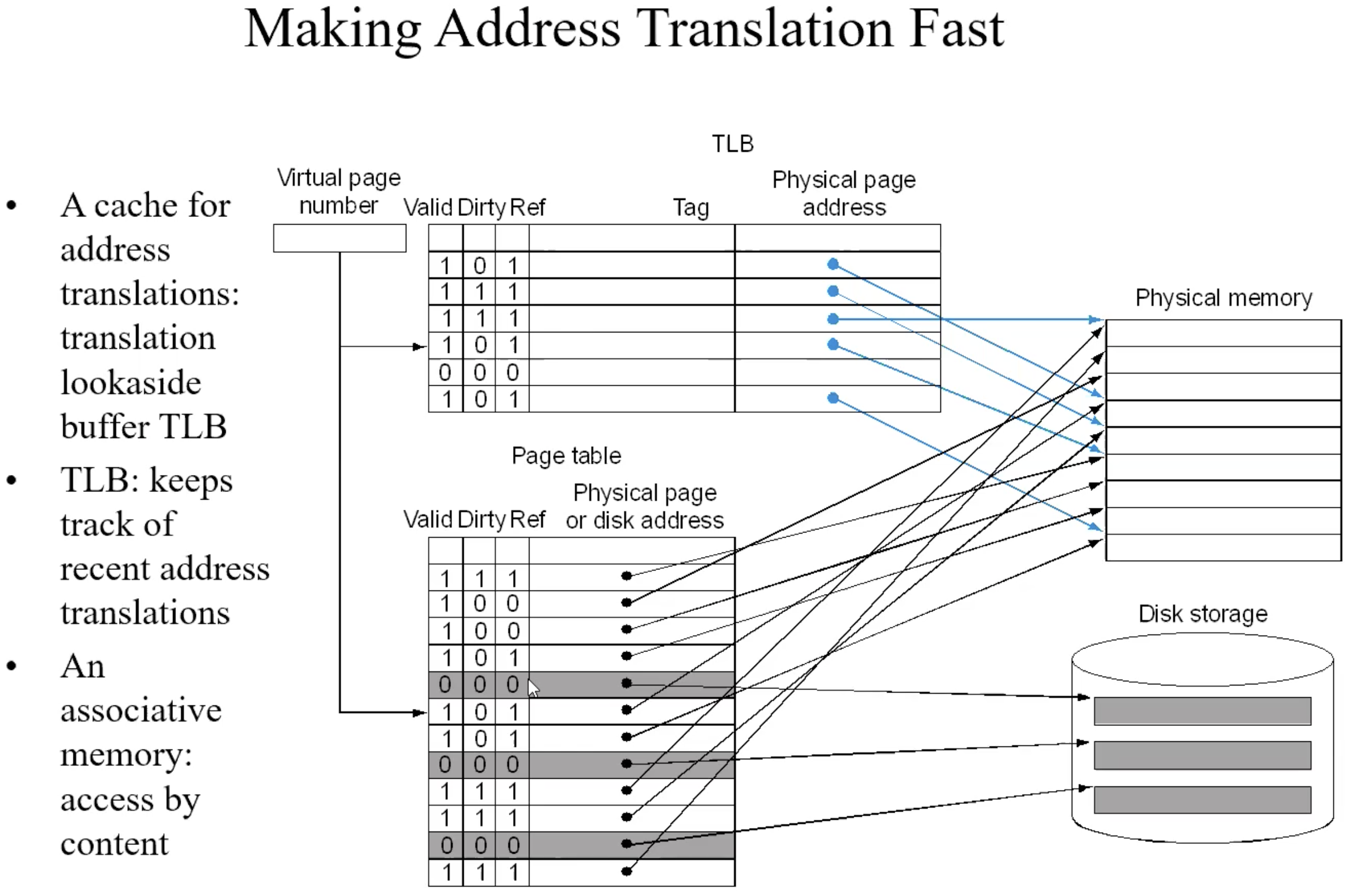
process of TLB
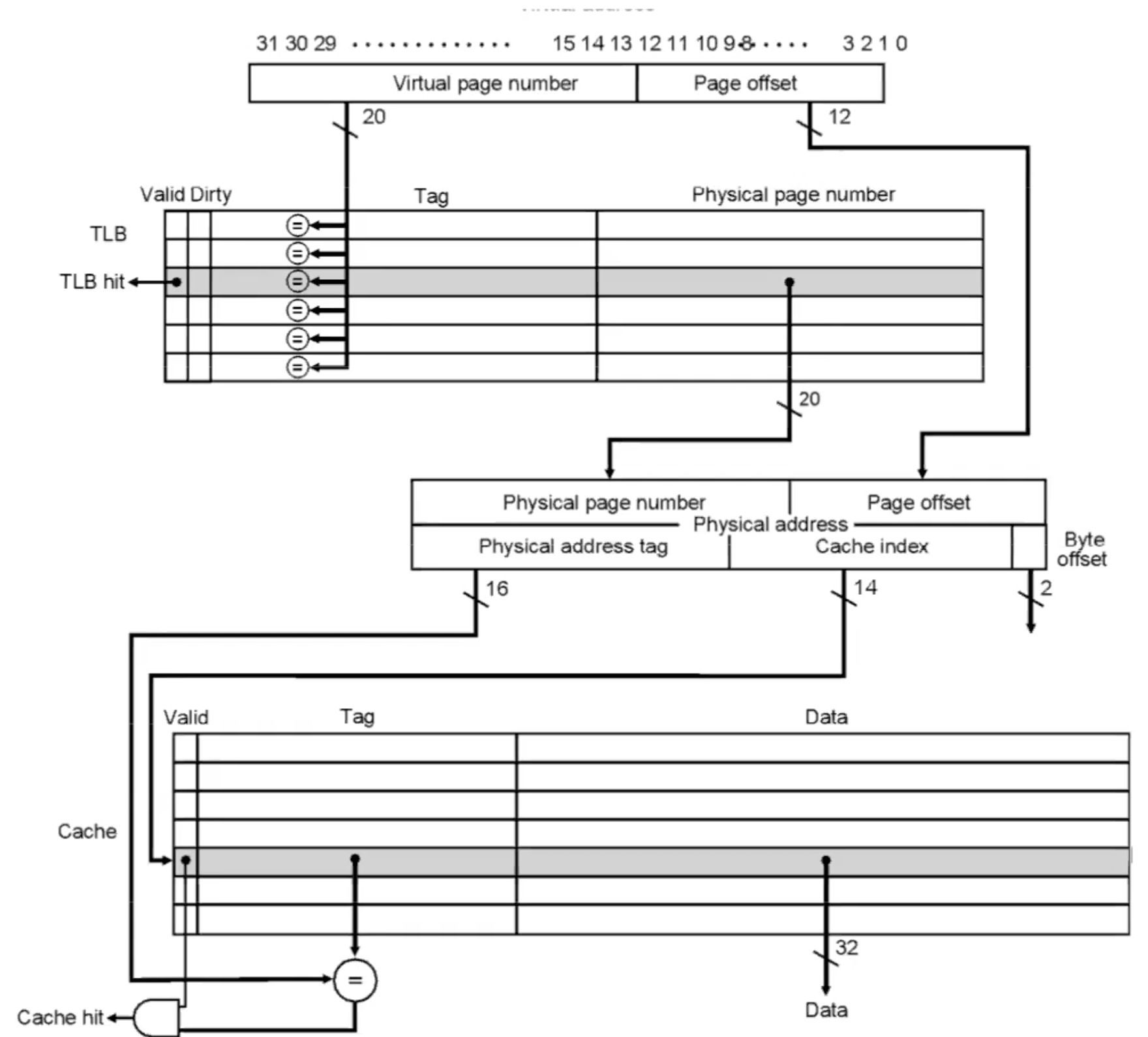
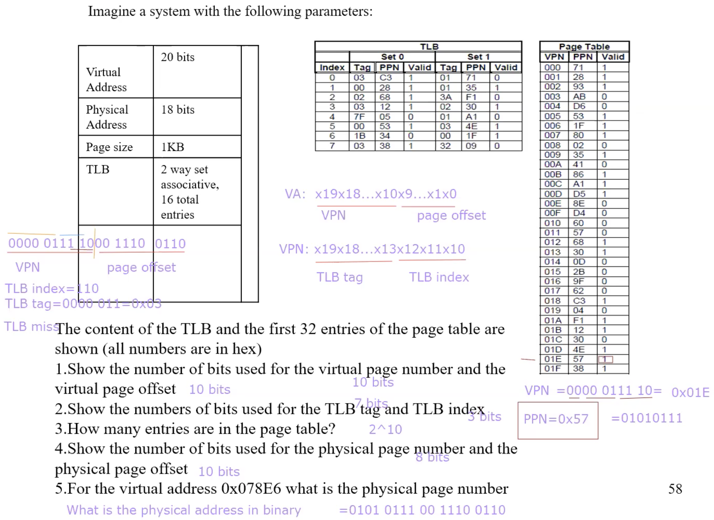
Example TLB translation
Chapter 3
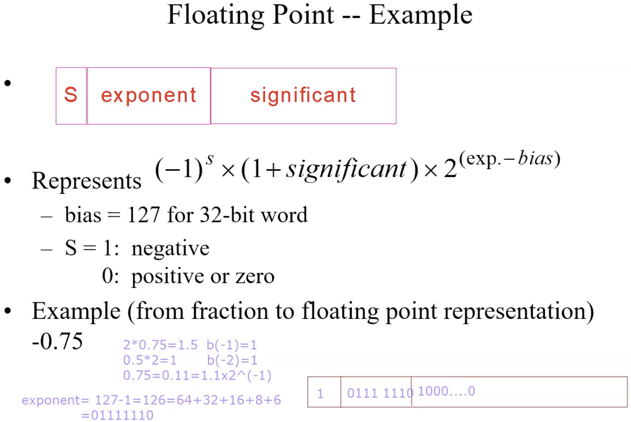
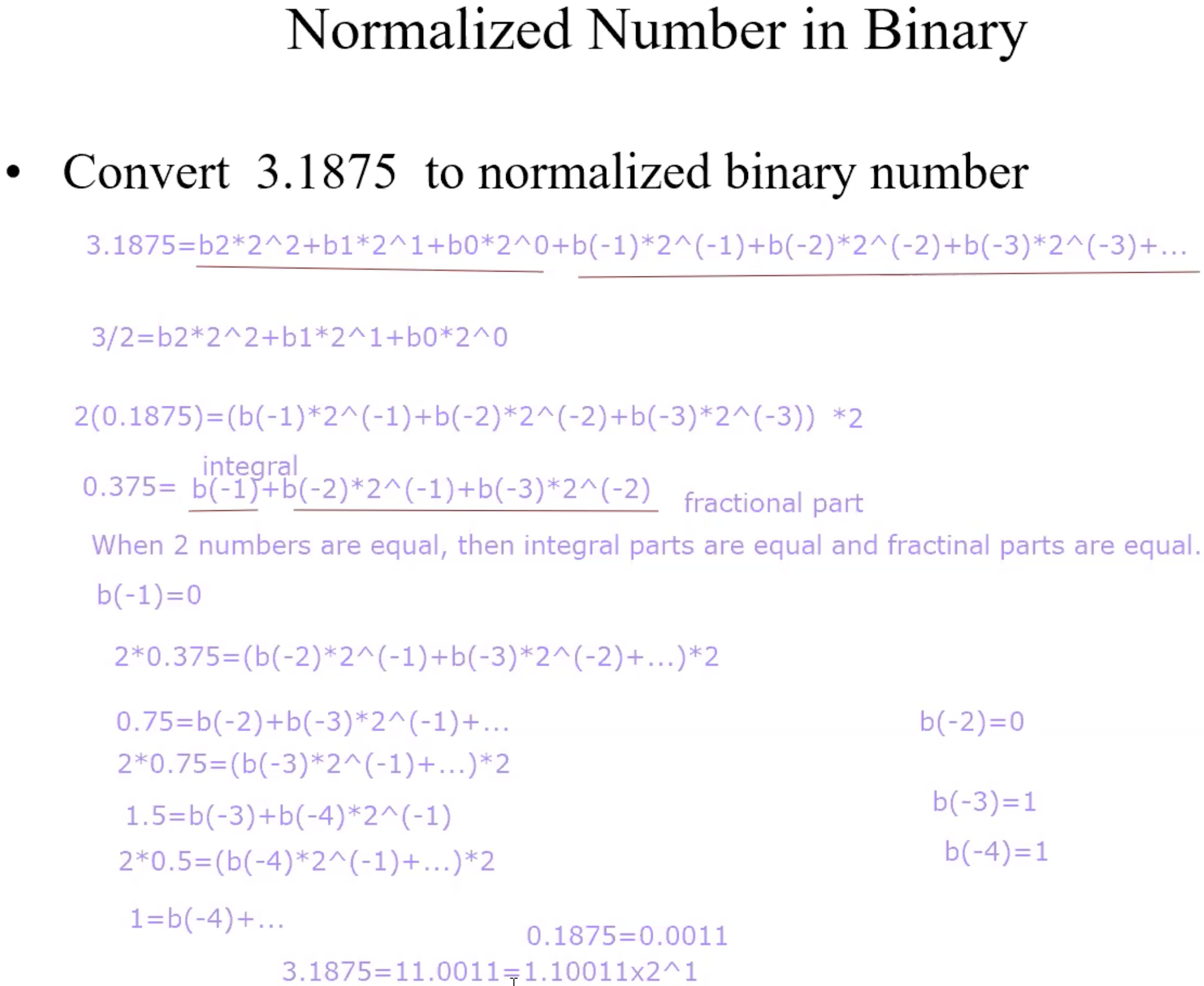
Normalized Number in Binary
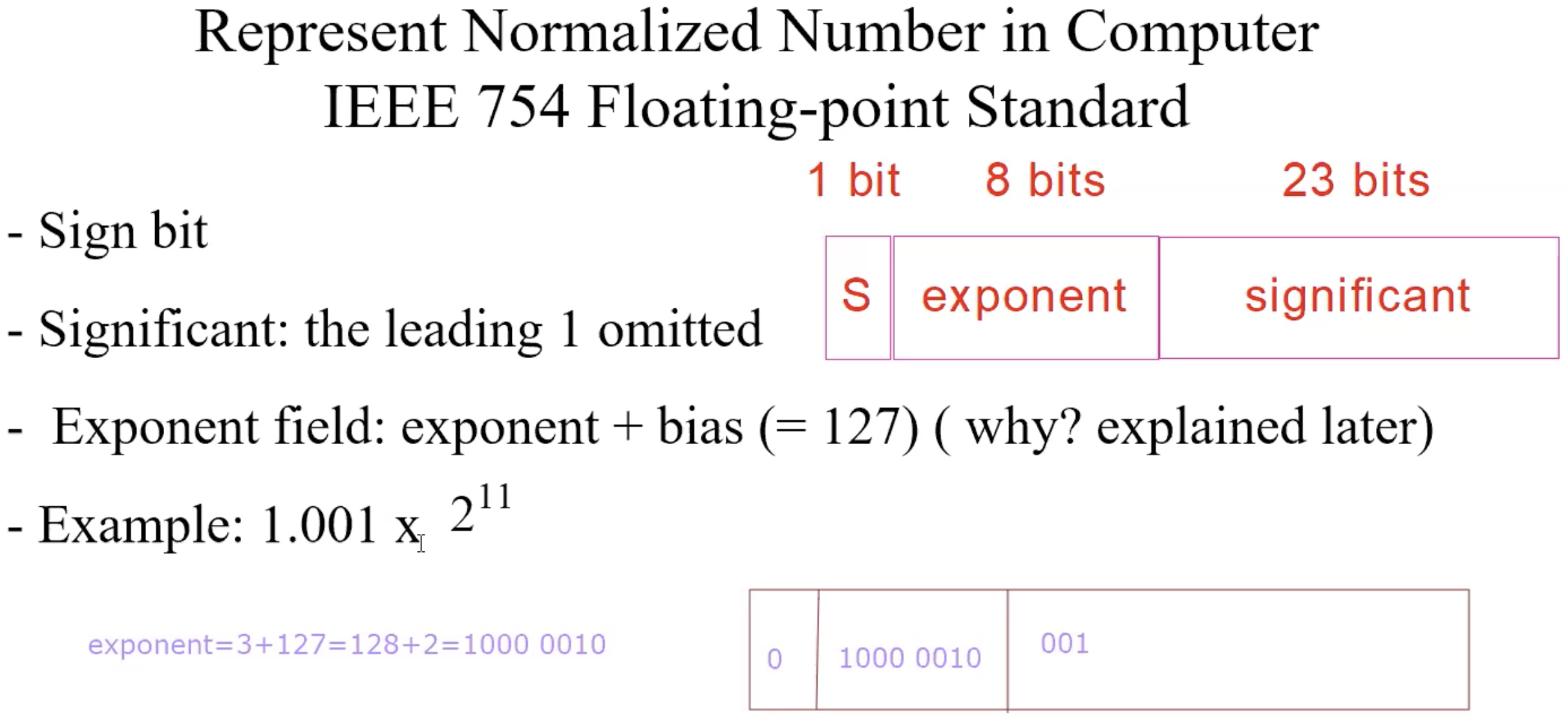
Represent Normalized Number in Computer IEEE
Why a bias
If we use 2’s complement for exponent, not good for sorting and comparison
0000 0000 most negative exponent
1111 1111 most positive exponent
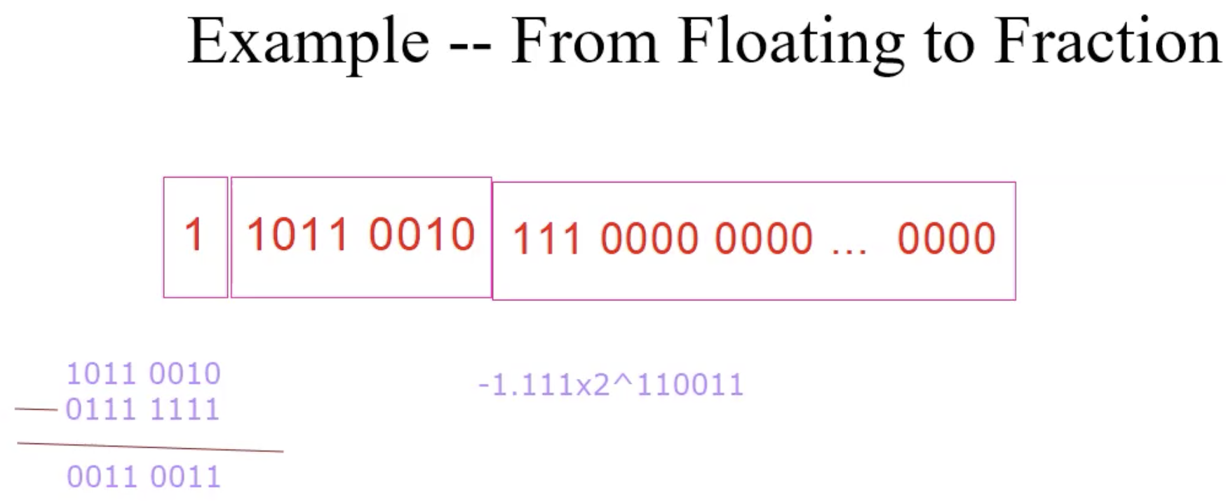
Example floating transition fraction